Optical fiber main distribution frame

A general distribution frame, optical fiber technology, applied in optics, light guides, optical components, etc., can solve the problems of inconvenient installation of LED lights, limited space, high processing defect rate, and achieve the effect of satisfying line transformation and transition and simple structure

Active Publication Date: 2017-09-15
NINGBO LINGTONG TELECOM EQUIP
View PDF5 Cites 0 Cited by
  • Summary
  • Abstract
  • Description
  • Claims
  • Application Information

AI Technical Summary

Problems solved by technology

[0002] The optical fiber main distribution frame is widely used in the optical communication terminal equipment in the optical fiber fusion splicing, wiring, dispatching and testing between optical fiber cables in the optical fiber access network. It is the hub of signal transmission, dispatching and replacement between optical signal transceiver devices. Optical signal scheduling, switching and other functions, according to different network layout methods, people have developed a variety of optical fiber distribution frames, common optical fiber distribution frames are mostly single-sided operation structures, and a small number of double-sided The side-operated optical fiber distribution frame is also limited to the terminal on one side, and the other side is only used for fiber routing management. Now there are in-line modules and horizontal modules in the distribution frame, sockets are set on the modules, and on the upper side of the modules Installing grooves are arranged on both sides of the wall, and LED display lights are arranged in the placing grooves. The LED display lights are used for the user to confirm the connection status of the optical cable connection, but the upper part of the module is very thin, so the installation groove is provided. Due to the limited space, it is very inconvenient to install LED lights, and the processing defective rate is high
In addition, after the current optical distribution frame is installed and fixed, the position is determined, and it is very troublesome to move or adjust the direction

Method used


Image

  • Optical fiber main distribution frame
  • Optical fiber main distribution frame
  • Optical fiber main distribution frame

Examples


Embodiment Construction

[0014] The present invention will be further described in detail below in conjunction with the accompanying drawings and specific embodiments.

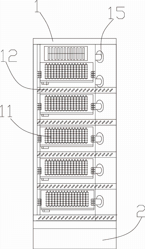
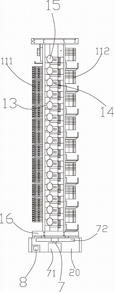
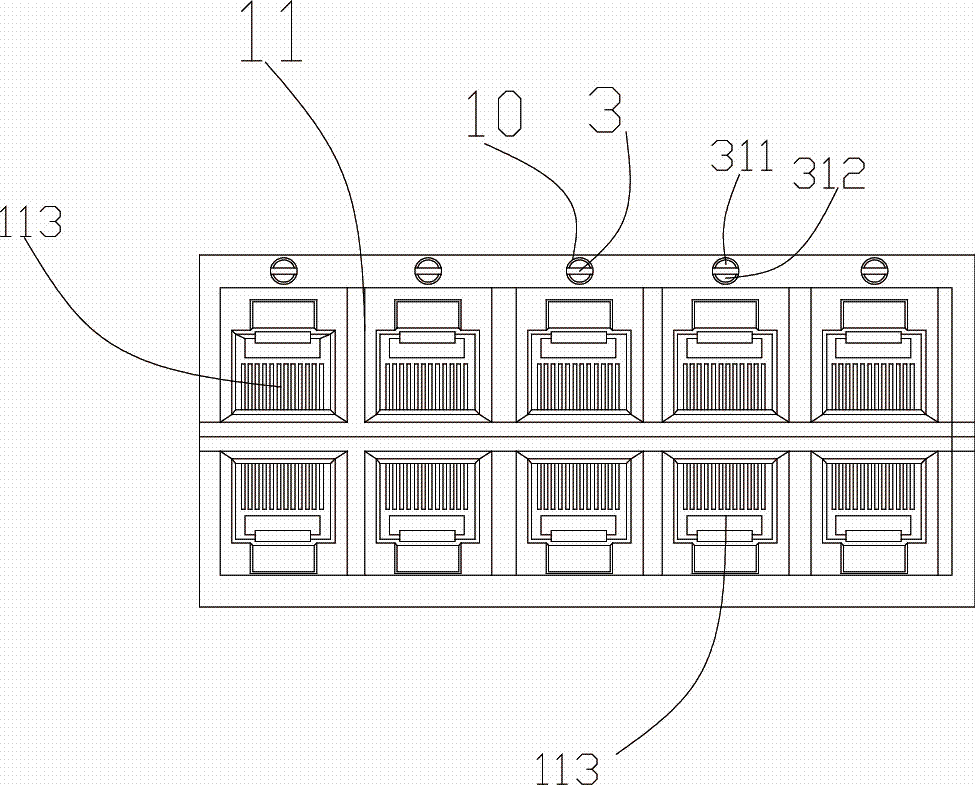
[0015] see figure 1 to Figure 4 As shown, the optical fiber main distribution frame includes a rack 1, and a module 11 is arranged on the rack 1, and the module 11 includes an in-line module 111 and a row module 112, and the in-line module 111 and the row module 112 They are respectively arranged on the front and rear surfaces of the rack 1. The row modules 111 include multi-layer row rows composed of 96-core terminal panels. Horizontal wire slots 12 are arranged under each row row. The row modules 111 are composed of A plurality of 72-core integrated machine frames are arranged vertically, and an optical cable fixing plate 13 is arranged on the side of the frame 1, and the optical cable fixing plate 13 is located at the upper or lower end of the in-line module 111. It is characterized in that , the side of the frame 1 is provided...


PUM


Abstract

The invention discloses an optical fiber main distribution frame and belongs to the technical field of optical fiber distribution. The optical fiber main distribution frame comprises a frame body. Modules are disposed on the frame body. A support plate is disposed at the lower end of the frame body. A fixing seat is disposed at the lower end of the support plate. A rotating mechanism is disposed in the fixing seat. An insertion opening is formed in each module. A through hole is formed above each insertion opening. Light guide bars penetrate the through holes. A liquid crystal block is disposed between the front light guide bar and the rear light guide bar. A bulb is disposed at the rear end of each module. The radian of the tail end of the rear light guide bar is consistent with each bulb. Compared with the prior art, the optical fiber main distribution frame has the advantages that the main distribution frame can be moved or the angles of the main distribution frame can be adjusted according to actual needs, the light of the turned-on bulbs irradiates the rear light guide bar, the rear light guide bar is brightened, a user can conveniently determine a connection state, and the optical fiber main distribution frame is simple in structure, convenient and practical.

Description

technical field [0001] The invention belongs to the technical field of optical fiber distribution, in particular to an optical fiber main distribution frame. Background technique [0002] The optical fiber main distribution frame is widely used in optical fiber fusion splicing, wiring, scheduling, and testing optical communication terminal equipment between optical fiber access network optical cables. It is a hub for signal transmission, scheduling, and replacement between optical signal transceiver equipment. Optical signal scheduling, switching and other functions, according to different network layout methods, people have developed a variety of optical fiber distribution frames, common optical fiber distribution frames are mostly single-sided operation structures, and a small number of double-sided The side-operated optical fiber distribution frame is also limited to the terminal on one side, and the other side is only used for fiber routing management. Now there are in-l...

Claims


Application Information

Patent Timeline
Patent Type & Authority Patents(China)
IPC IPC(8): G02B6/44
CPCF21V23/06G02B6/0091G02B6/4452
Inventor 邓奕丁高文雄林辉宣沈金标
Owner NINGBO LINGTONG TELECOM EQUIP
Why Eureka
Try Eureka