Eureka AIR delivers breakthrough ideas for toughest innovation challenges, trusted by R&D personnel around the world.

A panel lead detection device and detection method

A detection device and lead technology, which is applied in the measurement device, measurement electricity, nonlinear optics, etc., can solve the problems of poor lead detection and repair, low detection efficiency, and large detection error, so as to improve lead detection efficiency and reduce lead The effect of detection errors

Inactive Publication Date: 2017-04-26
HEFEI BOE OPTOELECTRONICS TECH +1
View PDF5 Cites 0 Cited by
  • Summary
  • Abstract
  • Description
  • Claims
  • Application Information

AI Technical Summary

Problems solved by technology

[0005] To sum up, in the process of detection and repair of defective leads in the lead area of ​​the panel in the prior art, manual line inspection is required when detecting the leads in the lead area of ​​the panel, so the detection efficiency is low, and the detection error is relatively large, and the Panel quality has a great influence

Method used


Image

  • A panel lead detection device and detection method
  • A panel lead detection device and detection method
  • A panel lead detection device and detection method

Examples


Embodiment 1

[0066] The test light collected by the detection device in the specific embodiment of the present invention is the transmitted light after the detection light passes through the lead wire to be tested. The detection device in the specific embodiment of the present invention determines that there is an abnormality in the lead wire to be detected in the lead wire area of ​​the panel, including: open circuit of the lead wire to be detected, short circuit of the lead wire to be detected, and foreign matter on the lead wire to be detected.

[0067] When the detection device in the specific embodiment of the present invention detects the lead wire to be detected in the lead wire area of ​​the panel, some parameters need to be initially set in the detection device, such as the detection device in the specific embodiment of the present invention according to the position coordinates of the lead wire to be detected, Parameters such as the shape of the lead wire to be detected, the lengt...

Embodiment 2

[0071] The test light collected by the detection device in the specific embodiment of the present invention is the reflected light after the detection light is reflected by the lead wire to be tested.

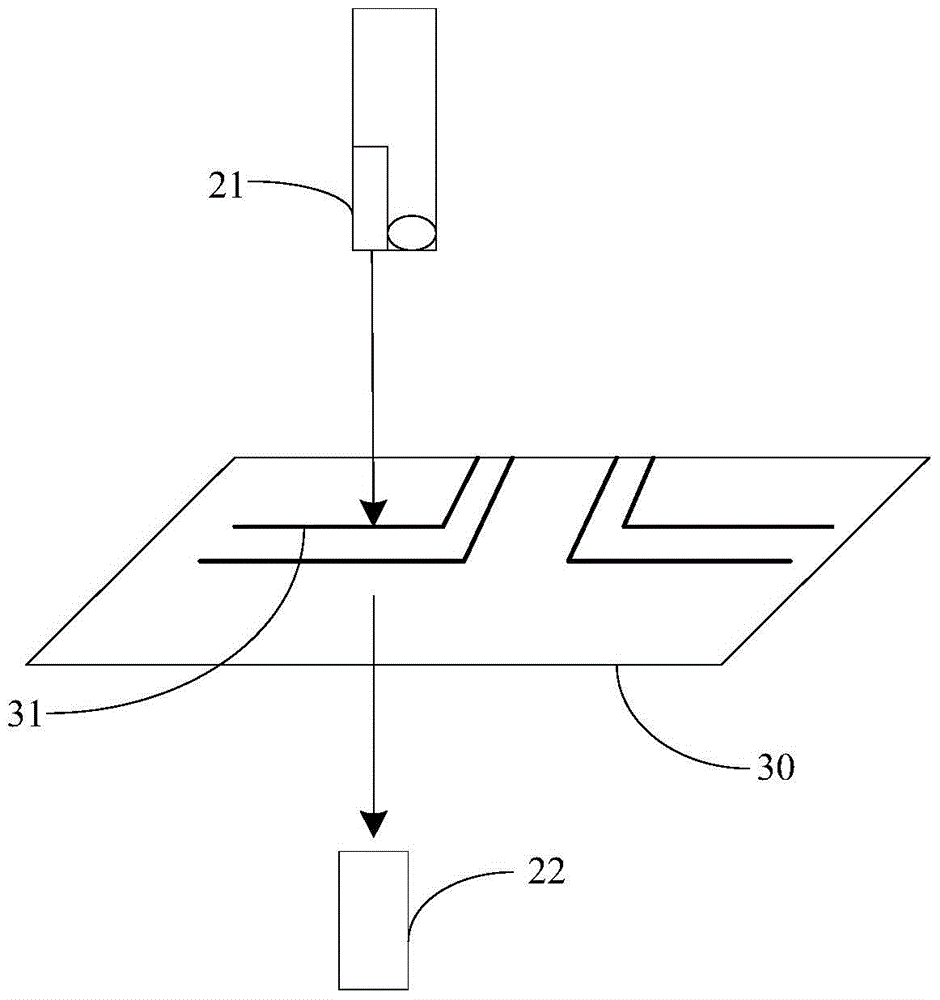
[0072] Such as Figure 6 As shown, when the specific embodiment of the present invention detects, the detection device first locks the initial position of the lead wire 31 to be detected; Light, the diameter of the spot 60 of the detection light is preset, preferably, the diameter d of the spot 60 of the detection light satisfies: d=L0; the detection device collects the reflected light after the detection light is reflected by the lead wire 31 to be detected, And test the intensity value of the reflected light, and use the intensity value of the reflected light obtained from the test as the initial intensity value.

[0073] Then, the detection device moves another step on the lead to be detected in the panel lead area according to the preset moving direction and moving step, a...


PUM


Abstract

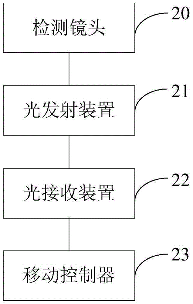
The invention discloses a panel lead wire detection device and a panel lead wire detection method. The panel lead wire detection device and the panel lead wire detection method are used to achieve automatic line tracking when used to detect lead wires, improve detection efficiency of the lead wires, and reduce detection error of the lead wires. The panel lead wire detection device comprises a detection lens used to detect the appearance of each lead wire to be detected in a panel lead wire area, a light emitting device used to emit detection light which irradiates the lead wires to be detected, a light reception device used to collect test light rays of the detection light after being processed by the lead wires to be detected and intensity value of the test light rays and a moving controller, wherein the light reception device compares the intensity value of the test light rays with initial intensity value which is preset, if the intensity value of the test light rays is not equal to the initial intensity value, the light reception device confirms that the lead wires to be detected are abnormal, and if not, the light reception device confirms that the lead wires to be detected are normal, and the moving controller is used to receive a control signal so as to control the detection lens to move for one step according to a preset moving direction and the preset moving step length if the light reception device confirms that the lead wires are normal, or control the detection lens to not move if the light reception device confirms that the lead wires are abnormal.

Description

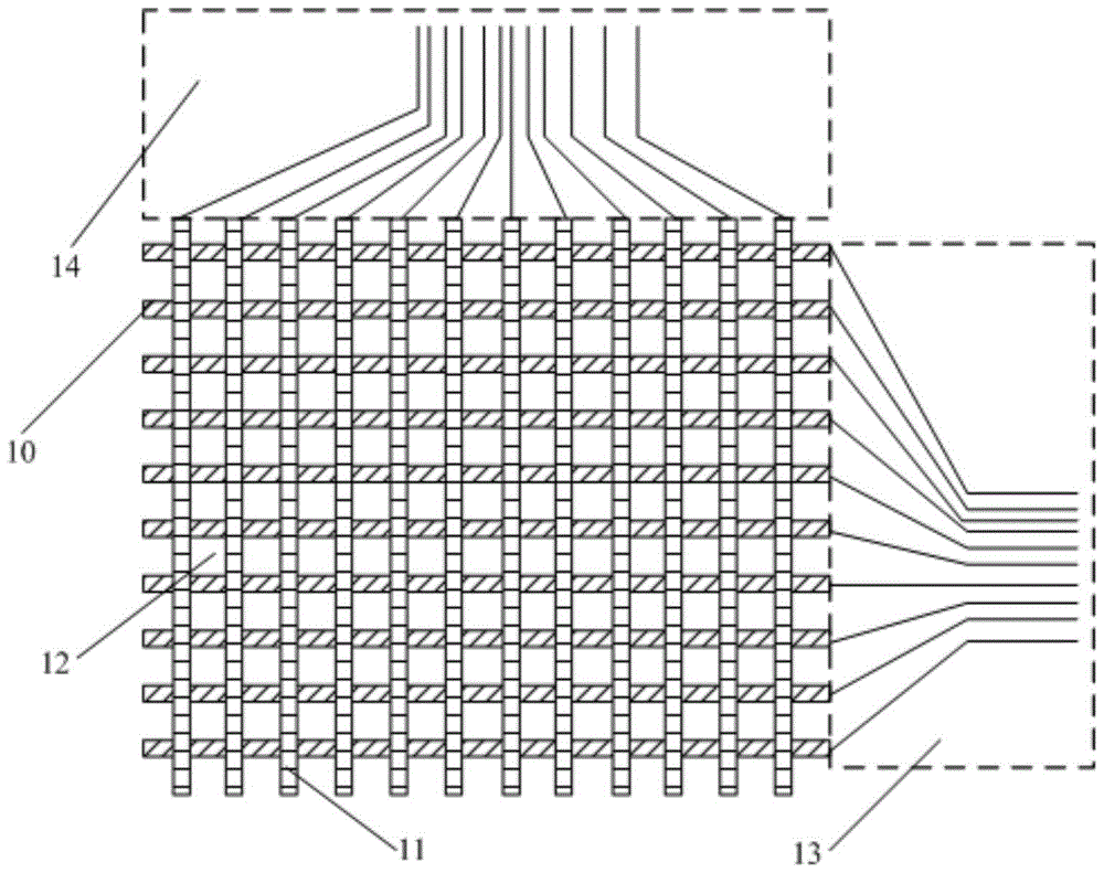
technical field [0001] The invention relates to the field of display technology, in particular to a panel lead detection device and detection method. Background technique [0002] In the design of each panel (Panel) of a Thin Film Transistor Liquid Crystal Display (TFT-LCD), each pixel in the Panel is driven in a line scanning manner. The TFT thin film transistors in the same row / column are driven by the same gate (Gate) / data (Date) line, and the mutual conduction of the Gate / Date line can precisely control each pixel. The signal line of each row / column is led out to the edge of the Panel, forming the panel lead area, such as figure 1 As shown, the leads of the Date line 10 form the Date lead area 13, the leads of the Gate line 11 form the Gate lead area 14, and the panel lead area includes the Date lead area 13 and the Gate lead area 14; the intersection between the Date line 10 and the Gate line 11 The area is the pixel area 12, the wires in the Date wire area 13 and the...

Claims


Application Information

Patent Timeline
Patent Type & Authority Patents(China)
IPC IPC(8): G02F1/13G01R31/02
CPCG02F1/1309G02F1/1362G02F1/136259G01R31/50G02F1/136254G02F1/136263
Inventor 夏龙
Owner HEFEI BOE OPTOELECTRONICS TECH
Why Eureka
Eureka Blog
Learn More