Voltage insulation monitoring device with function of voltage deviation compensation and voltage deviation compensation method thereof

An insulation monitoring device and voltage deviation technology, which is applied in the direction of circuit devices, emergency protection circuit devices, emergency protection devices with automatic disconnection, etc., can solve the problem of excessive voltage deviation of the DC system to the ground and hidden dangers left in the safe operation of the DC system, etc. problems, to achieve the effect of ensuring safe operation and eliminating potential safety hazards

Active Publication Date: 2015-04-08
SHANDONG ZHIYANG ELECTRIC
3 Cites 1 Cited by

AI-Extracted Technical Summary

Problems solved by technology

[0003] The DC insulation monitoring device can only detect the insulation degradation of the DC system, but when the DC system has a single-pole or two-pole insulation degradation, if the voltage deviation of th...

Method used

Wherein, switch K is connected to control unit M by digital-to-analog converter DAC, and digital-to-analog converter DAC converts the digital signal of control unit output into analog signal, so that positive and negative compensation triodes use; Described switch K adopts a relay, the normally open contact and normally closed contact of the relay are respectively connected w...

Abstract

The invention relates to a voltage deviation regulator for an insulation monitoring device, in particular to an insulation monitoring device with the function of voltage deviation compensation. The insulation monitoring device comprises a balance bridge circuit and a compensation circuit; the compensation circuit comprises an anodic compensation triode and a cathodic compensation triode; a collector of the anodic compensation triode is connected to an anode of a direct current bus; an emitter of the anodic compensation triode is connected to a ground wire through a current limiting resistor R3; a collector of the cathodic compensation triode is connected to the ground wire; an emitter of the cathodic compensation triode is connected to a cathode of the direct current bus through a current limiting resistor R4; a base of the anodic compensation triode and a base of the cathodic compensation triode are connected to a changeover switch respectively through a current limiting resistor R5 and a current limiting resistor R6; the changeover switch is connected to a control unit. Deviation of voltage-to-earth of a direct-current system is precisely compensated. The invention further provides a voltage deviation compensation method; current between the collectors and the emitters is smoothly controlled, running safety of the direct current system is guaranteed, and safety hazards are eliminated.

Application Domain

Technology Topic

Insulation monitoring deviceCurrent limiting +10

Image

  • Voltage insulation monitoring device with function of voltage deviation compensation and voltage deviation compensation method thereof

Examples

  • Experimental program(2)

Example Embodiment

[0025] Example 1:
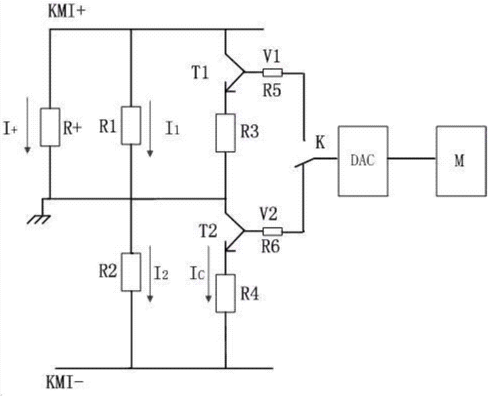
[0026] Such as figure 1 As shown, the insulation monitoring device with voltage deviation compensation of the present invention includes an insulation monitor and a balance bridge circuit, as well as a compensation circuit and a control unit. The compensation circuit includes a positive compensation triode T1 and a negative compensation triode T2, and a positive compensation triode T1 The collector is connected to the positive KMI+ of the DC bus, the emitter is connected to the ground through the current limiting resistor R3, the collector of the negative compensation transistor T2 is connected to the ground, and the emitter is connected to the negative KMI- of the DC bus through the current limiting resistor R4, positive and negative. The base of the compensating transistor is connected to the switch K through the current-limiting resistor R5 and the current-limiting resistor R6, and the switch K and the insulation monitor are connected to the control unit M.
[0027] Wherein, the switch K is connected to the control unit M through a digital-to-analog converter DAC, and the digital-to-analog converter DAC converts the digital signal output by the control unit into an analog signal for use by the positive and negative compensation transistors; the switch K uses a relay , The normally open and normally closed contacts of the relay are respectively connected to the current-limiting resistor R6 and current-limiting resistor R5, the relay coil is connected to the control unit M, and the control unit M switches the compensation transistor connected to the control unit M according to the current circuit conditions, The control unit M is a single-chip microcomputer, such as the 51 series, which is widely used and low in cost.
[0028] The balance bridge circuit of the present invention is composed of a balance resistor R1 connected to the positive pole of the DC bus KMI+ and the ground wire, and a balance resistor R2 connected to the negative pole KMI- of the DC bus and the ground wire. Normally, the positive and negative poles are compensated The base voltage of the triode is 0, both work in the cut-off area, no current flows between the collector and the emitter, the resistance of the DC bus positive to ground and the DC bus negative to ground resistance monitored by the insulation monitor are sent to Control unit M.
[0029] Such as figure 1 , Assuming that the resistance of the DC bus positive KMI+ to ground is R+, when R+ decreases, the voltage deviation between the positive and negative poles of the DC bus will be too large. According to Kirchhoff’s law, the sum of the current flowing through the balance resistor R1 and the DC bus positive KMI+ resistance to ground R+ is equal to the current flowing through the balance resistor R2, which can be written as I 1 +I + = I 2. At this time, the switch K is connected to the negative compensation transistor T2 and the control unit, and the output voltage V2 of the digital-to-analog converter is adjusted through the control unit to make the negative compensation transistor T2 work in the amplifying area. At this time, the negative compensation transistor T2 is between the collector and the emitter. There will be a current I C Flow through, when I C The size of I + When they are the same, the voltage between the positive and negative poles of the DC bus can be balanced to the ground, and the voltage deviation to the ground can be accurately compensated.

Example Embodiment

[0030] Example 2:
[0031] This embodiment provides a voltage deviation compensation method based on Embodiment 1, including the following steps:
[0032] In the first step, the insulation detection device transmits the collected DC bus positive-to-ground resistance R+ and DC bus negative-to-ground resistance R- to the control unit;
[0033] In the second step, the control unit judges the resistance of the DC bus positive to ground resistance R+ and the DC bus negative to ground resistance R-. If the control unit detects that the DC bus positive to ground resistance R+ decreases, the control unit M controls the switch K Connect with the current limiting resistor R6, adjust the output voltage V2 of the digital-to-analog converter DAC, control the current through the current limiting resistor R4 to be equal to the current through the resistor R+, if the control unit M detects the DC bus negative resistance to ground R -Lower, the control unit M controls the switch K to connect with the current limiting resistor R5, adjusts the output voltage V1 of the digital-to-analog converter DAC, and controls the current through the current limiting resistor R3 to equalize the current through the resistor R- to complete the compensation .
[0034] The regulation principle of the output voltage V2 of the digital-to-analog converter is:
[0035] Negative compensation triode base current I B =(V2–U BEQ )/(R6+(1+β)R 4 ), the current I between the collector and the emitter C =(1+β)*I B , Where U BEQ The voltage drop between the base and collector of the negative electrode compensation transistor is a fixed value, β is the magnification of the negative electrode compensation transistor, which is also a fixed value. R6 and R4 are known values. When the value of R+ is obtained, the resistance R+ is obtained Current I+, I+ and I C The values ​​are equal, V2=I C /(1+β)*(R6+(1+β)R 4 )+U BEQ , The control unit adjusts according to the calculated value of V2.
[0036] Similarly, the adjustment principle of the output voltage V1 of the digital-to-analog converter is:
[0037] Positive compensation triode base current I B =(V1–U BEQ )/(R5+(1+β)R3), the current I between collector and emitter C =(1+β)*I B , Where U BEQ The voltage drop between the base and collector of the negative electrode compensation transistor is a fixed value, β is the magnification of the negative electrode compensation transistor, which is also a fixed value. R5 and R3 are known values. When the R-value is obtained, the resistance R is obtained. -Current I-, I- and I C The values ​​are equal, V1=I C /(1+β)*(R6+(1+β)R 4 )+U BEQ , The control unit adjusts according to the calculated value of V1.
[0038] The switch K uses a relay. The normally open and normally closed contacts of the relay are respectively connected to the current-limiting resistor R6 and the current-limiting resistor R5. The relay coil is connected to the control unit M. The control unit M switches the current limit by controlling the energization of the relay coil For the connection of resistor R6 and current limiting resistor R5, the control unit M can be a single-chip microcomputer, or a PLC can be selected.
[0039] The invention utilizes the working characteristics of the triode to realize the smooth control of the current between the collector and the emitter, and combines the use of Kirchhoff's law to accurately compensate the deviation of the DC system's ground voltage to ensure the safe operation of the DC system, Eliminate safety hazards.

PUM

no PUM

Description & Claims & Application Information

We can also present the details of the Description, Claims and Application information to help users get a comprehensive understanding of the technical details of the patent, such as background art, summary of invention, brief description of drawings, description of embodiments, and other original content. On the other hand, users can also determine the specific scope of protection of the technology through the list of claims; as well as understand the changes in the life cycle of the technology with the presentation of the patent timeline. Login to view more.

Similar technology patents

USBKey safe protection method

Owner:INDUSTRIAL AND COMMERCIAL BANK OF CHINA

Free-piston type internal combustion engine

InactiveCN101328855AImprove performanceGuaranteed safe operationIgnition automatic controlAutomatic controlLinear displacementCombustion chamber
Owner:SHANGHAI JIAO TONG UNIV

Classification and recommendation of technical efficacy words

  • Eliminate potential safety hazards
  • Guaranteed safe operation

Voice recognition method based on mobile terminal and mobile terminal

ActiveCN101840700AEnhanced sensing abilityEliminate potential safety hazardsVibration measurement in solidsSubstation speech amplifiersLoudnessEnvironmental sounds
Owner:YULONG COMPUTER TELECOMM SCI (SHENZHEN) CO LTD

Fiber monitoring system

InactiveCN103647601AAccurately determine the location of the faultGuaranteed safe operationFibre transmissionVIT signalsControl bus
Owner:STATE GRID CORP OF CHINA +2

Anomalous video warning device for ATM

InactiveCN101609581APrevention and reduction of illegal activitiesGuaranteed safe operationComplete banking machinesBurglar alarmEvent analysisReal-time computing
Owner:YUNNAN ZHENGZHUO INFORMATION TECH
Why Eureka
Try Eureka