Cutting machine equipment for electrode material and electrode piece manufacturing equipment

A technology for electrode materials and manufacturing equipment, applied in the field of electrode parts manufacturing equipment, can solve problems such as looseness, wrinkles, and poor extension of the coating part, and achieve the effect of inhibiting electrode materials

Active Publication Date: 2015-04-15
HIATACHI POWER SOLUTIONS CO LTD
View PDF8 Cites 3 Cited by
  • Summary
  • Abstract
  • Description
  • Claims
  • Application Information

AI Technical Summary

Problems solved by technology

If such a difference in length occurs, it will become the main cause of wrinkles in the electrode material
[0005] That is, when there is a coated area where the foil is stretched by rolling and an uncoated area where the foil is not stretched, when the rolled electrode material is conveyed, only the uncoa

Method used


Image

  • Cutting machine equipment for electrode material and electrode piece manufacturing equipment
  • Cutting machine equipment for electrode material and electrode piece manufacturing equipment
  • Cutting machine equipment for electrode material and electrode piece manufacturing equipment

Examples


Embodiment 1

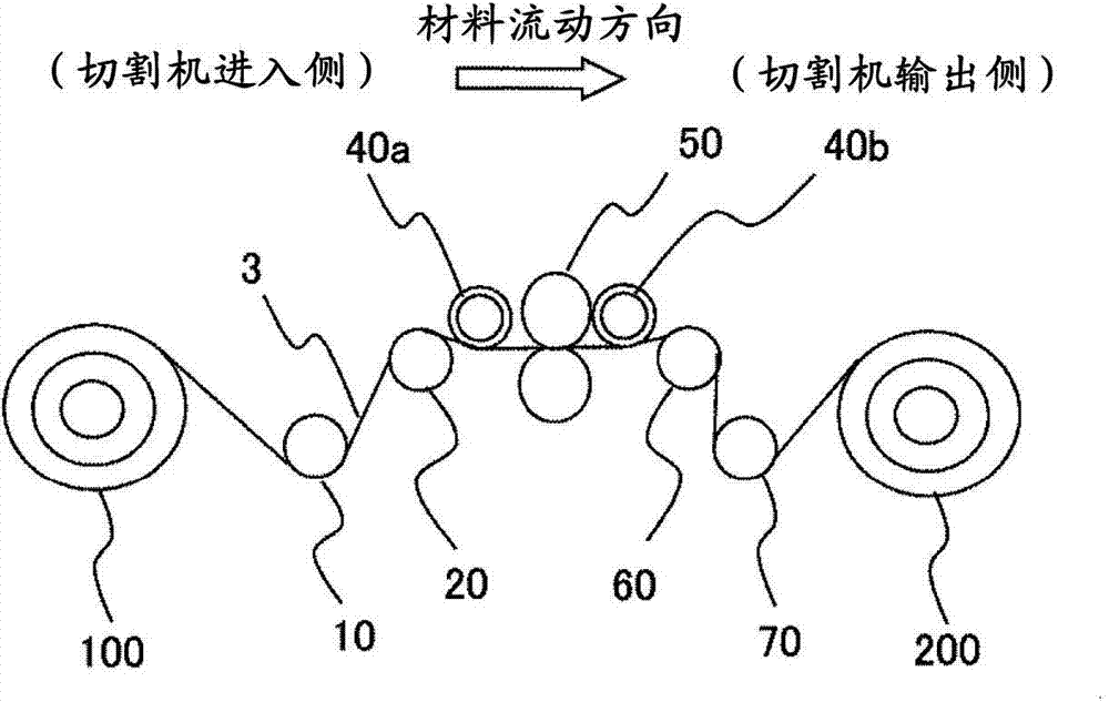
[0036] figure 1 The general outline of the cutter facility for electrode materials which concerns on one Example of this invention is shown. The entry side of the cutting machine 50 is provided with an unwinding machine 100, which is equipped with a coil that will be wound in a coil shape of electrode materials such as lithium-ion secondary battery electrode parts that have been rolled, and the output side of the cutting machine 50 is provided with a winding machine 100. Machine 200, which winds the cut electrode material. The winder 200 may wind up the cut electrode material by a shared winder, or a plurality of winders may be installed to wind up the cut electrode material respectively.

[0037]Any of razor type, scissor type, and multi-knife type can be applied to the cutter part of the cutting machine. Existing equipment can be used for the cutting machine, and detailed description is omitted here. In addition, as described above, in the case of an electrode material (s...

Embodiment 2

[0058] Although the cutting machine equipment for electrode materials of the present invention can also be installed in the line of rolling equipment for electrode materials, as described above, it is desirable to install the electrode materials separately in consideration of stopping the cutting machine equipment due to wear of the cutter blade, etc. Use cutting machine equipment and roll pressing equipment for electrode materials.

[0059] However, when looking at the whole electrode material manufacturing facility, it is necessary to consider the conveyance of the electrode material after the electrode material is rolled by the rolling equipment. That is, countermeasures against wrinkles, cracks, and the like of the electrode material generated by rolling equipment for the electrode material are desired. In particular, the demand for a high compressibility has increased in recent years. In such a case, it is particularly important to convey the rolled electrode material wit...


PUM


Abstract

The invention provides cutting machine equipment for an electrode material, cuts an electrode material having a coating part and non-coating part which is subjected to roller pressing, the abovementioned coating part is a coating part of electrode active material, even if an extensive quantity difference in a material length direction is generated in a material width direction due to roller pressing, generation of flashings or burrs can also be inhibited and the electrode material is cut. Between guide rollers which are arranged in front of and behind a cutting machine and the cutting machine, and in front of and behind or either thereof of the cutting machine, is additionally provided with an elastic guide roller which performs elastic deformation through tension generated on the electrode material. In addition, roller pressing equipment for the electrode material and cutting machine equipment for the electrode material are arranged respectively, all the guide rollers of the roller pressing equipment for the electrode material which are used in a process of carrying the electrode material after roller pressing adopt elastic guide rollers which perform elastic deformation through tension generated on the material.

Description

technical field [0001] The present invention relates to a cutter device for electrode materials and an electrode member manufacturing device, and more particularly to a cutter device for electrode materials that cuts rolled electrode materials and an electrode member manufacturing device equipped with the device. Background technique [0002] The positive electrode or negative electrode material of a lithium ion battery, capacitor, etc. is a material obtained by coating an electrode active material on both sides of a strip-shaped substrate such as aluminum foil, copper foil (metal foil current collector). In addition, the electrode material is rolled (compressed) by a rolling device so that the density of the active material is increased and the thickness is made uniform. The electrode material is provided with an uncoated portion not coated with an active material on both side portions in the width direction of the base material in order to secure a joint portion for weldin...

Claims


Application Information

Patent Timeline
IPC IPC(8): B26D7/00H01M4/00H01M4/04H01M4/139
CPCY02E60/122Y02E60/10
Inventor 多田健一郎山我拓渡边修平
Owner HIATACHI POWER SOLUTIONS CO LTD
Why Eureka
Try Eureka