Construction machine

A technology of construction machinery and body, applied in construction, cranes, earth movers/excavators, etc., can solve the problems of increased accelerator pedaling, higher costs, and the inability to realistically change opening characteristics, etc., to improve operability, The effect of a simple and low-cost structure

Inactive Publication Date: 2015-04-15
DAIKIN IND LTD
View PDF6 Cites 3 Cited by
  • Summary
  • Abstract
  • Description
  • Claims
  • Application Information

AI Technical Summary

Problems solved by technology

[0013] In addition, since the opening characteristic of the control valve 3 is determined by the groove-shaped passage formed by machining of the spool valve, the opening characteristic cannot be easily changed, and it is determined according to the condition of the flat ground of the machine body with high operating frequency.
In other words, if the opening characteristic of the control valve 3 is to be changed, the control becomes extremely complicated and the cost becomes high, and the opening characteristic cannot be changed realistically.
[0014] On the other hand, the operating conditions of hydraulic excavators vary greatly depending on the work site, and the operability may be greatly deteriorated depending on the combination of conditions such as the working posture and working conditions.
[0015] For example, in the case where the hydraulic motor 2 is used to perform a swing operation on the machine body, if the control valve 3 is set according to the most suitable conditions for the swing operation on flat ground, then in the operation on the sloped ground, the load increases. When operating sideways, there is a problem that due to the increase of the load on the flat ground, a higher than usual operation amount is required, and the operability deteriorates.
This is because, for example, it becomes the same state as when the car starts on a hill with an increased amount of accelerator pedal, and the operability deteriorates.

Method used


Image

  • Construction machine
  • Construction machine
  • Construction machine

Examples


no. 1 approach

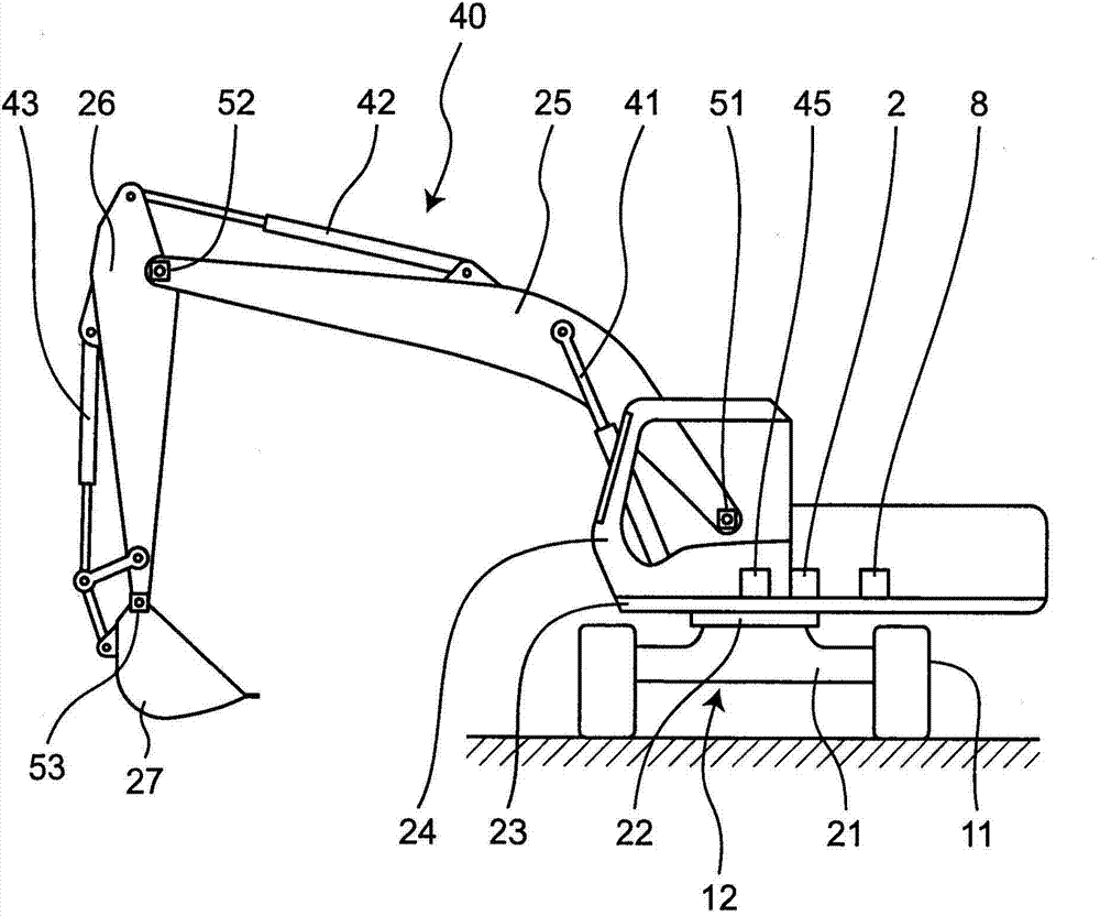
[0081] Such as figure 1 As shown, a hydraulic excavator as an example of the construction machine of the first embodiment includes a traveling device 11 and a body 12 provided on the traveling device 11 , and the body 12 has a lower portion 21 supported by the traveling device 11 ; An upper turntable 23 is provided on the lower part 21 so as to be able to turn by means of a turn mechanism 22 . A cab 24 is provided on one side in front of the turntable 23 , and a boom 25 is provided at the front center of the turntable 23 so as to be able to pitch. An arm 26 is provided at the front end of the boom 25 so as to be rotatable up and down, and a bucket 27 is provided at the front end of the arm 26 so as to be rotatable.

[0082] The boom 25 is pitched by the boom hydraulic cylinder 41 , the arm 26 is rotated by the arm hydraulic cylinder 42 , and the bucket 27 is rotated by the bucket hydraulic cylinder 43 . The hydraulic cylinders 41, 42, 43 described above are examples of actu...

no. 2 approach

[0099] A hydraulic excavator as an example of the construction machine of the second embodiment, according to figure 1 The output of the boom rotation angle sensor 51 is shown to Figure 5 The illustrated pattern of the discharge amount of the hydraulic pump 1 at the time of correction is different from the hydraulic excavator of the first embodiment only in that the pattern is further corrected.

[0100] Therefore, since the hardware of the second embodiment is the same as that of the first embodiment, citing Figure 1~3 , Figure 5 And its description, only the different structures will be described below.

[0101] The second embodiment of Figure 8 The flow chart shown is the same as that of the first embodiment Figure 4 The flow chart shown is only the same as that in which step S5 is added. Figure 4 Because they are different, steps S1 to S4 are omitted by citing the description of the first embodiment, and only step S5 will be described below.

[0102] The contr...


PUM


Abstract

The present invention provides a construction machine, which improves the operability of a remote controller by using a simple and chip structure regardless of the attitude of the body of the construction machine. A controller (70) performs corrective control on the output of a hydraulic pump (1) corresponding to the attitude of a machine body (12) according to an operation signal of a remote controller (5) and the output of a gyro sensor (8). Therefore, since the corrective control of the output of the hydraulic pump (1) is carried out according to the attitude of the machine body (12), operability equivalent as on a normal horizontal plane can be ensured with a simple and chip structure even in the cases that the machine has various attitudes, such as on a inclined plane, so that the operability of the remote controller (5) is improved.

Description

technical field [0001] The present invention relates to construction machines such as hydraulic excavators, cranes and the like. Background technique [0002] Conventionally, as a construction machine, there is a construction machine described in JP-A-4-366235 (Patent Document 1). [0003] This conventional construction machine includes: a traveling device; a revolving body on the traveling device; a gyro sensor that detects the inclination angle of the revolving body; an operating mechanism consisting of a boom, an arm, and a bucket attached to the revolving body; a hydraulic actuator for the arm, a hydraulic actuator for the arm, and a hydraulic actuator for the bucket; a flow directional control valve that controls flow and direction to the hydraulic actuator for the boom; and a control unit that controls flow according to The output of the gyro sensor is used to control the flow direction control valve. [0004] In addition, when the swing body is raised by a predeterm...

Claims


Application Information

Patent Timeline
Patent Type & Authority Applications(China)
IPC IPC(8): E02F9/22B66C13/20B66C13/16B66C23/86
Inventor 濑川均
Owner DAIKIN IND LTD
Why Eureka
Try Eureka