Electric clipper control system

A control system and technology of electric scissors, applied in the direction of use feedback control, etc., can solve problems such as low safety factor, hidden safety hazards, and limited customer demand, and achieve the goals of avoiding hidden dangers, safe use, and efficient cutting work Effect

Inactive Publication Date: 2015-04-15
宁波市镇海长城汽车摩托车部件厂
View PDF4 Cites 5 Cited by
  • Summary
  • Abstract
  • Description
  • Claims
  • Application Information

AI Technical Summary

Problems solved by technology

At the same time, there is a limitation of this solution, that is, the microprocessor failure handling
When the microprocessor fails due to signal interference, it may issue a wrong command, that is, when the switch of the pruning shears is not pressed, the microprocessor sends a command to make the motor rotate, t

Method used


Image

  • Electric clipper control system
  • Electric clipper control system
  • Electric clipper control system

Examples


Embodiment 1

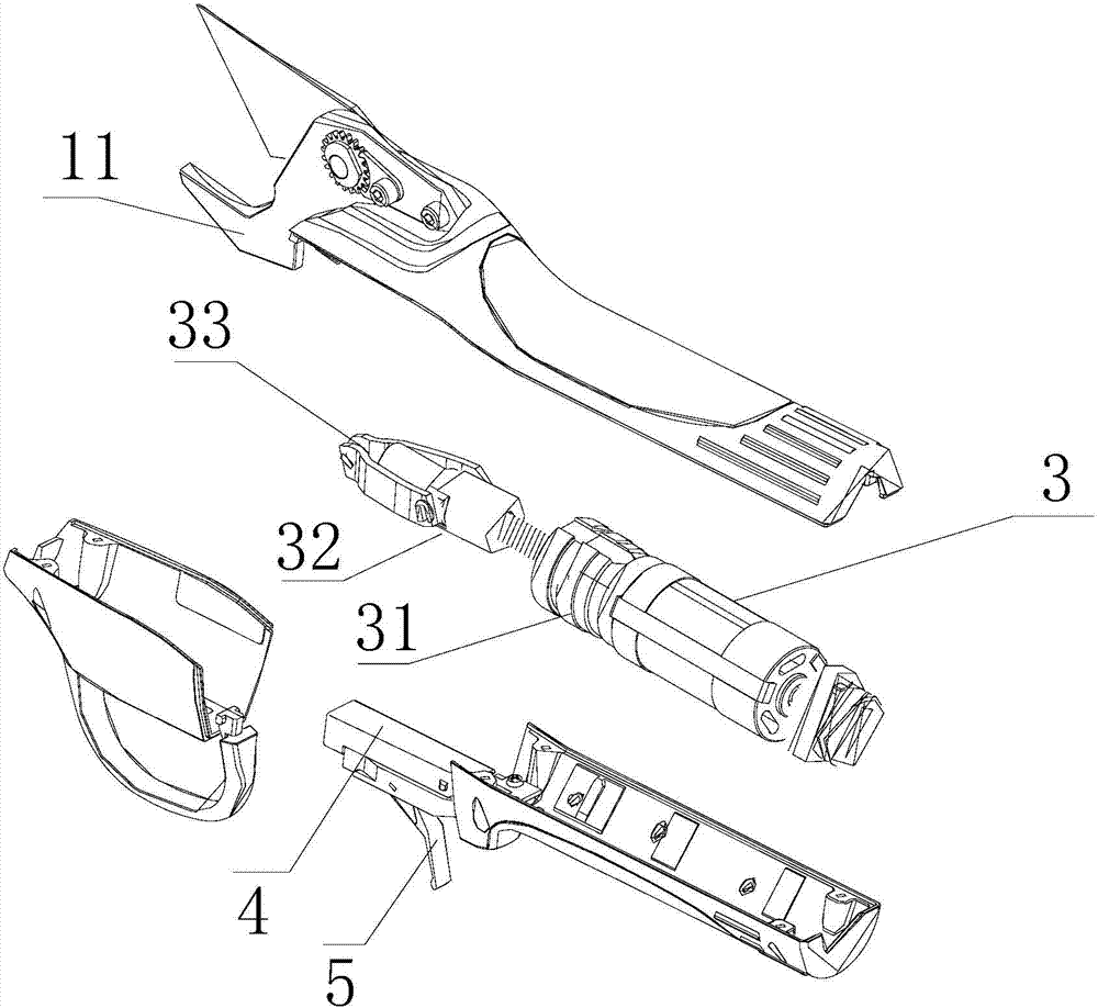
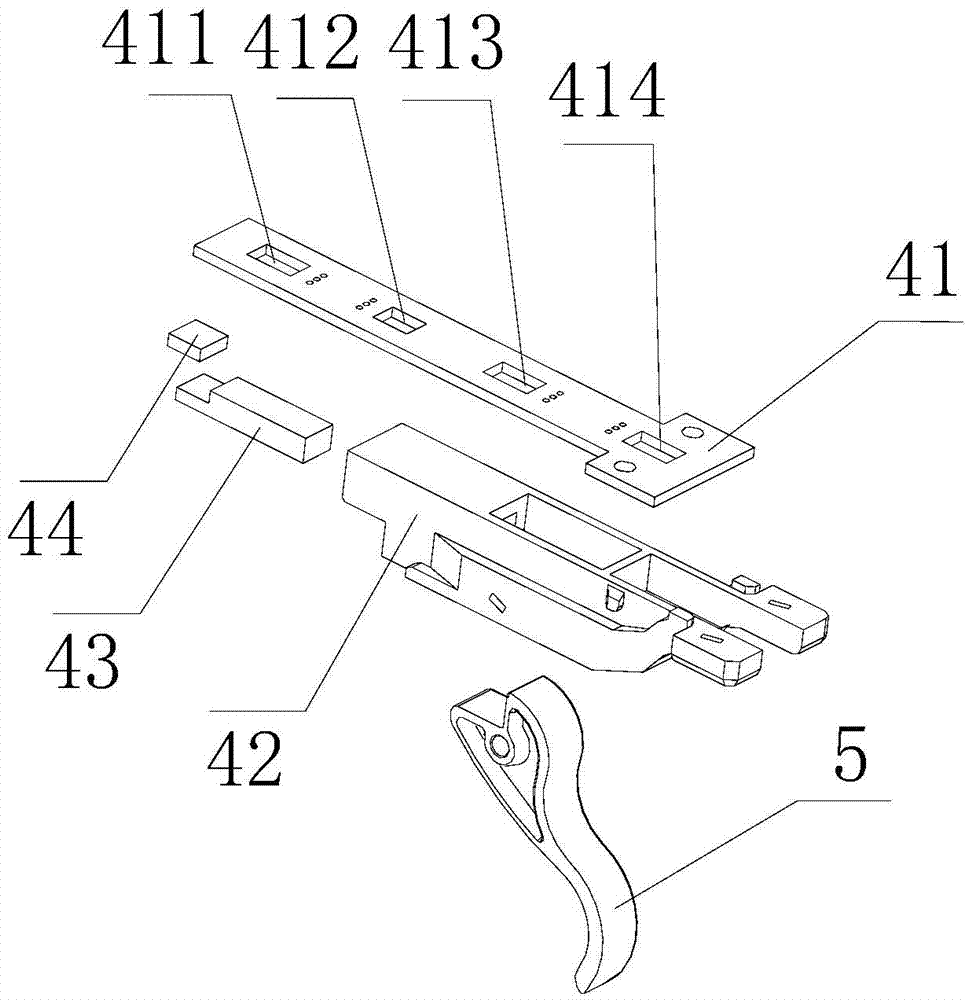
[0021] refer to Figure 1 to Figure 3 As shown, it is an electric scissors applying the control system of the present invention. The electric scissors are driven by a motor 3 housed in the scissors main body. The motor 3 is connected with a reducer 31. The end of the rod 32 is connected with a connector 33 for driving the opening and closing angle of the scissors head 11. The electric scissors have two opening modes, a large opening and a small opening, and the switching of the opening mode of the scissors head is realized through a control system. The system includes a sensing device 4 for sensing the trigger position and a controller for receiving the sensing signal of the sensing device 4, wherein the sensing device 4 is a Hall travel plate 41 with a plurality of positions and cooperates with it A magnet 44 that can slide thereon, the magnet 44 is fixed on the magnet holder 43 in the trigger bracket 42, one end of the magnet holder 43 is fixedly connected with the return sp...

Embodiment 2

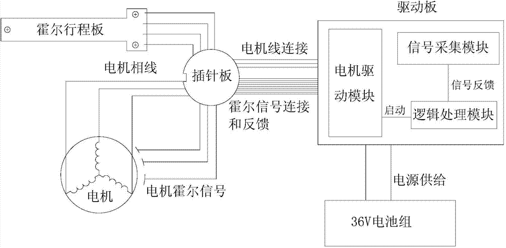
[0029] Such as Figure 4 As shown, as the second preferred embodiment of the present invention, the control system includes a servo frequency conversion processor, the input end of the servo frequency conversion processor is connected to a DC power supply, and the output end of the servo frequency conversion processor is connected to a three-phase AC servo motor. The servo frequency conversion processor is also connected with three control switches, which are start switch, forward rotation switch and reverse switch. The start switch is used to control the running state of the whole system. When the start switch is in the enable position, the system circuit is connected, and the DC The power supply inputs the DC voltage into the servo frequency conversion processor. After the servo frequency conversion process, the DC voltage is converted from DC input to AC output to drive the three-phase AC servo motor, so that the three phases of the three-phase AC servo motor start at the sa...


PUM


Abstract

The invention discloses an electric clipper control system, relates to the industrial control field, and solves the problems that the prior art is single in cutting mode and big in safety troubles; the control system comprises a hall sensor used for sensing a trigger station and a controller receiving a hall signal of the hall sensor; the hall sensor comprises a hall stroke plate provided with a plurality of stations and a magnet matched with the hall stroke plate; when the trigger drives the magnet to different stations, the hall stroke plate senses a corresponding hall signal and inputs the hall signal into the controller; the controller outputs a corresponding control signal to control a rotary angle and a rotary direction of a brushless motor, thus controlling a cutting motion of a clipper head; the control system can realize full range opening and half range opening of the electric clipper head, and has current limit protection effect; when the trigger is buckled for two times after starting, the clipper head can fully open so as to remind a user to start cutting work, thus preventing safety troubles, and usage is safer.

Description

technical field [0001] The invention relates to the field of industrial control, in particular to an electric scissors control system capable of improving the safety factor of electric scissors and enabling switching of opening modes of scissor heads. Background technique [0002] As a category of electric tools, electric scissors include electric scissors for cutting thick fibers such as carpets, electric scissors for cutting cables, and electric scissors for pruning branches. These electric scissors usually consist of a fixed blade and a movable blade forming a cutting edge between the two blades. The movable blade swings back and forth under the forward and reverse drive of the motor, so that the knife edge is opened and closed continuously. In order to reduce accidents during use, electric scissors must meet the requirements of safety standards. Taking pruning shears for pruning branches as an example, the safety standard stipulates that once the switch is disconnected...

Claims


Application Information

Patent Timeline
IPC IPC(8): G05D3/12
Inventor 方培锵
Owner 宁波市镇海长城汽车摩托车部件厂
Why Eureka
Try Eureka