

Current limit control method and current limit control device of three-level inverter
A three-level inverter and current-limiting control technology, applied in the electronic field, can solve problems such as positive and negative busbar mutual irrigation, output voltage waveform difference, single-side busbar is large, etc., to prevent overvoltage, good output waveform, avoid Effects of too frequent movements
- Summary
- Abstract
- Description
- Claims
- Application Information
AI Technical Summary
Problems solved by technology
Method used
Image

Examples
Embodiment Construction
[0051] The present invention will be further explained below in conjunction with the accompanying drawings and embodiments, taking the resistive load as an example.
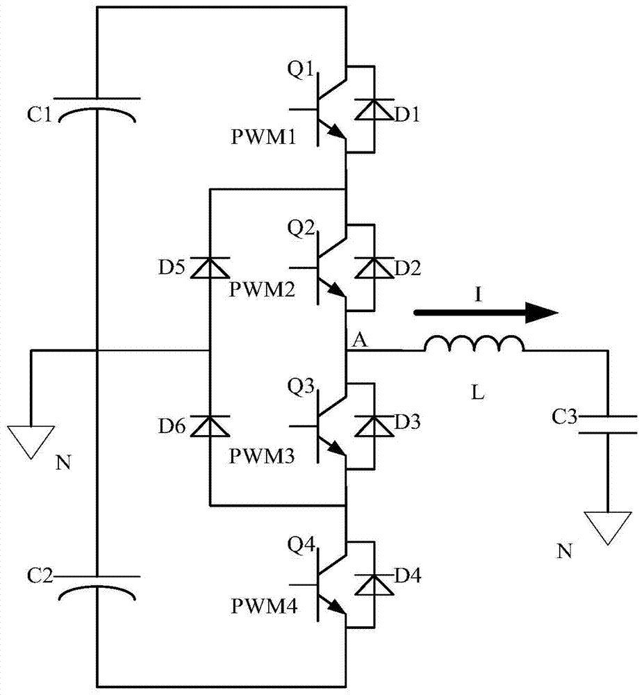
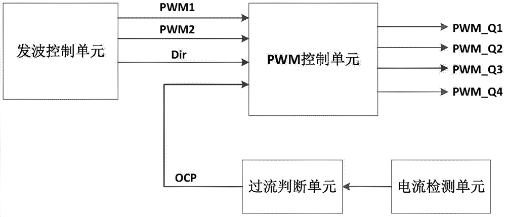
[0052] see figure 1 , the three-level inverter at least includes a bridge arm composed of four switching tubes connected in series in sequence, the four switching tubes are the main switching tube Q1 and the auxiliary switching tube Q2 located in the upper bridge arm, and the main switching tube located in the lower bridge arm Tube Q4 and auxiliary switch tube Q3. see figure 2 , in the current limiting control system of the three-level inverter, the wave control unit is used to output the direction signal (Dir) that the current voltage is in the positive half cycle or negative half cycle, and two complementary PWM signals with dead zones to the PWM The control unit is the PWM signal of the main switching tube—PWM1, and the PWM signal of the auxiliary switching tube—PWM2. The PWM control unit generates four PW...
PUM
 Abstract
Description
Claims
Application Information