Robot

A technology of robots and moving mechanisms, applied in the field of robots, can solve the problems of low rigidity, narrow range of posture changes, embedding failure, etc., and achieve the effect of high rigidity and wide range of motion

Active Publication Date: 2015-04-15
FUJITSU LTD
View PDF15 Cites 1 Cited by
  • Summary
  • Abstract
  • Description
  • Claims
  • Application Information

AI Technical Summary

Problems solved by technology

[0011] However, the above-mentioned parallel-linked robot has a narrow range of posture change, and also a narrow range of motion in the vertical direction.
[0012] In addition, since the parallel link robot can carry a small weight, the above-mentioned robot with a posture changing mechanism with three degrees of freedom at the front end of the parallel link robot has low rigidity.
Therefore, in the work in which the robot requires motion accuracy, for example, in the work of fitting a part into a recess, the position of the part may deviate and the fitting into the recess may fail.

Method used


Image

  • Robot
  • Robot
  • Robot

Examples


Embodiment Construction

[0028] Below, based on the attached drawings, while referring to Figure 1 to Figure 7 A robot according to an embodiment of the present invention will be described.

[0029] The robot according to the present embodiment is an industrial robot suitable for assembly work of devices having relatively small components such as personal computers and mobile phones, especially for work requiring operational precision.

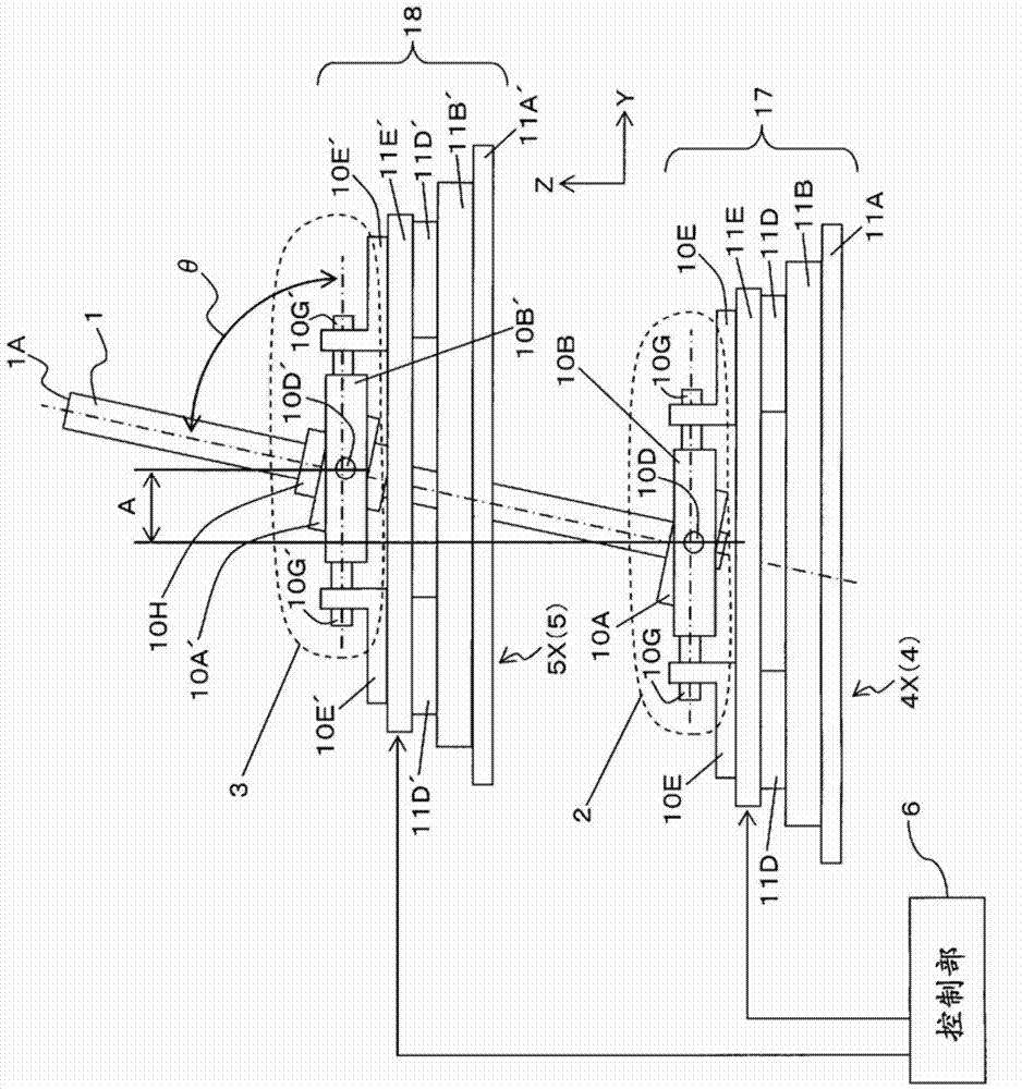
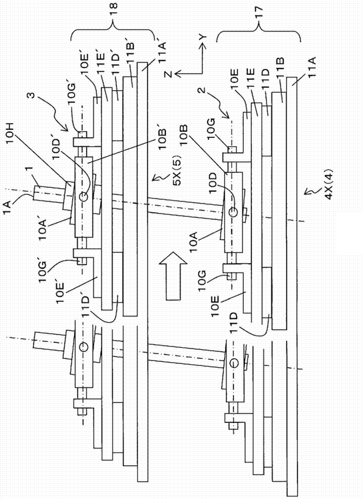
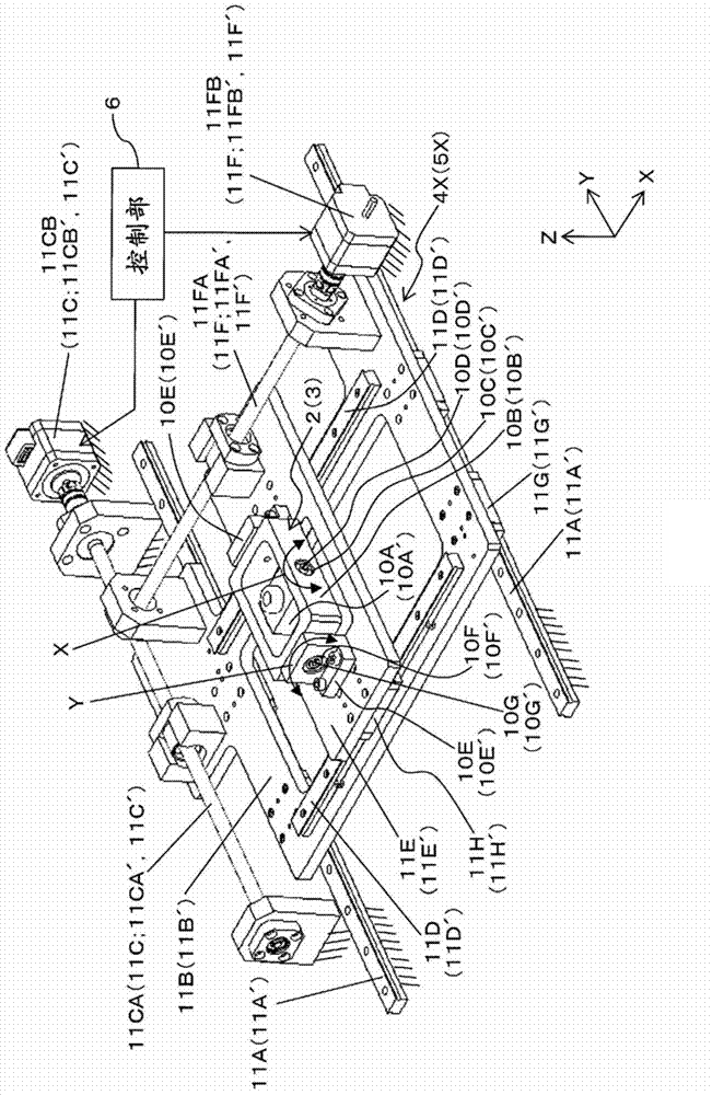
[0030] Such as figure 1 As shown, the robot of this embodiment includes a tool shaft 1 , a first support mechanism 2 , a second support mechanism 3 , a first in-plane movement mechanism 4 , a second in-plane movement mechanism 5 , and a control unit 6 .

[0031] Here, the tool shaft 1 is a shaft on which various tools, tables, etc. are attached to the front end 1A. For example, an end effector such as an air chuck, a table for holding a workpiece, and the like are attached to the front end 1A of the tool shaft 1 .

[0032] The first support mechanism 2 is attached...


PUM


Abstract

A robot comprises: a tool shaft (1); a first support mechanism (2), mounted on one section of the tool shaft, and tiltably supporting the tool shaft; a second support mechanism (3), mounted on another section of the tool shaft, and tiltably supporting the tool shaft; a first in-plane movement mechanism (4) for moving the first support mechanism in a first plane; a second in-plane movement mechanism (5) for moving the second support mechanism in a second plane; and a controller (6) for controlling the in-plane position and tilt angle of the tool shaft by controlling the first in-plane movement mechanism and second in-plane movement mechanism. The first support mechanism or the second support mechanism supports the tool shaft to be moveable in the axial direction.

Description

technical field [0001] The present invention relates to robots. Background technique [0002] In robots such as industrial robots, high speed, high precision, high degrees of freedom, and a wide range of motion are required. [0003] For example, in high-speed packaging work, etc., a parallel link robot excellent in high speed is used. [0004] In recent years, a robot having a three-degree-of-freedom posture change mechanism at the front end of a parallel link robot has been developed and used for, for example, assembly work. [0005] Patent Document 1: Japanese Patent Application Laid-Open No. 10-146789 [0006] Patent Document 2: Japanese Unexamined Patent Publication No. H10-213403 [0007] Patent Document 3: Japanese Patent Application Laid-Open No. 11-77577 [0008] Patent Document 4: Japanese Patent Laid-Open No. 2011-230241 [0009] Patent Document 5: Japanese Patent Laid-Open No. 2010-184328 [0010] Patent Document 6: Japanese Patent Application Laid-Open No....

Claims


Application Information

Patent Timeline
IPC IPC(8): B25J9/02
CPCB25J17/0275B25J9/048Y10S901/14Y10S901/19Y10S901/23B25J9/02
Inventor 武田郁夫
Owner FUJITSU LTD
Why Eureka
Try Eureka