Power transfer structure of vehicle

a technology of power transfer and vehicle, which is applied in the direction of jet propulsion mounting, couplings, transportation and packaging, etc., can solve the problems of increasing vibrations and noise in the interior of the vehicle and effectively achieving a vibration damping function. , to achieve the effect of effectively absorbing torsional vibration, increasing the size of the vehicl

Inactive Publication Date: 2018-07-17
MAZDA MOTOR CORP
View PDF7 Cites 1 Cited by
  • Summary
  • Abstract
  • Description
  • Claims
  • Application Information

AI Technical Summary

Benefits of technology

[0024]First, according to the first aspect of the present invention, since the dampers are arranged on at least two of the first, second, and third power transfer shafts, at least two dampers are provided on the drive shaft. Further, the respective dampers function in different frequency regions. Therefore, as compared to a conventional structure in which vibrations in a wide frequency region from a low frequency to a high frequency are absorbed by a single damper, the size increase of each of the dampers can be suppressed while satisfactorily maintaining a vibration damping performance of each of the dampers.
[0025]Further, according to the first aspect of the present invention, among the at least two dampers on the drive shaft, the predetermined damper (hereinafter may be referred to as a “low-frequency damper”) which requires a relatively large axial size for effectively achieving a vibration damping function in a low frequency region is arranged on the longest one of the at least two power transfer shafts. Therefore, it is unnecessary to extend the other power transfer shaft or change the layout of vehicle body members provided around the long low-frequency damper, and the long low-frequency damper can be provided on the drive shaft so as to be displaced from the vehicle body members in the axial direction. In addition, since the size increase of each of the dampers is suppressed as described above, the interference of the dampers arranged on the drive shaft with the vehicle body members can be suppressed.
[0026]According to the second aspect of the present invention, the predetermined damper (low-frequency damper) includes the small-diameter portion formed in a predetermined range in the axial direction, and the torsional rigidity of the predetermined damper is reduced by the small-diameter portion. Therefore, the damper can effectively absorb the torsional vibration that is especially problematic in the low frequency region. Further, the predetermined damper (low-frequency damper) is made of metal. Therefore, even when the predetermined damper is provided on the first power transfer shaft extending under the exhaust pipe of the engine, characteristics thereof are less likely to be changed by heat transferred from the exhaust pipe, and therefore, an excellent vibration absorbing function can be achieved for a long period of time.
[0027]According to the third aspect of the present invention, unlike the predetermined damper (low-frequency damper) made of metal, the remaining damper provided on at least one of the second power transfer shaft and the third power transfer shaft is configured to damp vibrations by the rubber member. Therefore, the remaining damper can effectively absorb the vibrations in a high frequency region which cannot be absorbed by the predetermined damper. Further, the damper including the rubber member is arranged at the second or third power transfer shaft which is arranged so as to be displaced from the exhaust pipe of the engine in the axial direction. Therefore, the deterioration of the rubber member by the heat transferred from the exhaust pipe can be suppressed, and the vibration absorbing function can be satisfactorily maintained for a long period of time.
[0028]In the power transfer structure of the vehicle according to the fourth aspect of the present invention, the elastic damper is provided between the first universal joint on the drive shaft and the second universal joint located at the driving wheel side of the first universal joint. Therefore, if a portion of the drive shaft which portion is located at the driving wheel side of the first universal joint swings vertically in accordance with irregularities on a road surface, and an outer diameter of the elastic damper is uniform, a movable range of the elastic damper in an upward / downward direction becomes maximum at a driving wheel-side end portion of the elastic damper which portion is the farthest from the first universal joint. According to the present invention, a portion of the elastic damper which portion is located at the driving wheel side of the elastic member is the small-diameter portion. With this, a maximum width of the movable range of the elastic damper is suppressed. On this account, interference between the elastic damper and vehicle body members provided around the elastic damper is easily avoided.
[0029]In addition, since the small-diameter portion is provided so as to be displaced from the elastic member in the axial direction, an outer diameter of the small-diameter portion can be effectively reduced regardless of the thickness of the elastic member. Therefore, the interference between the small-diameter portion of the elastic damper and the vehicle body members can be easily avoided while realizing the effective vibration absorption by the elastic member.

Problems solved by technology

However, when the reduced cylinder operation or the HCCI combustion is performed, the combustion of the engine tends to become unstable, and vibrations by torque fluctuation or the like tend to increase.
When the vibrations transferred to the drive shaft are transferred through a suspension arm and the like to a vehicle body, they become a cause of unpleasant vibrations and noise in a vehicle interior.
However, when the torque converter is in a lockup state or when a power train does not include the torque converter, the engine and the transmission are directly coupled to each other, so that the absorption of the vibrations by the torque converter cannot be realized.
Therefore, when a lockup range is expanded for the improvement of the fuel efficiency or when the torque converter is omitted by, for example, realizing multistage of an automatic transmission, problems of the above vibrations and noise become more serious.
When such vibrations are transferred through the drive shaft to the vehicle body, the same problems as above occur.

Method used


Image

  • Power transfer structure of vehicle
  • Power transfer structure of vehicle
  • Power transfer structure of vehicle

Examples


embodiment 1

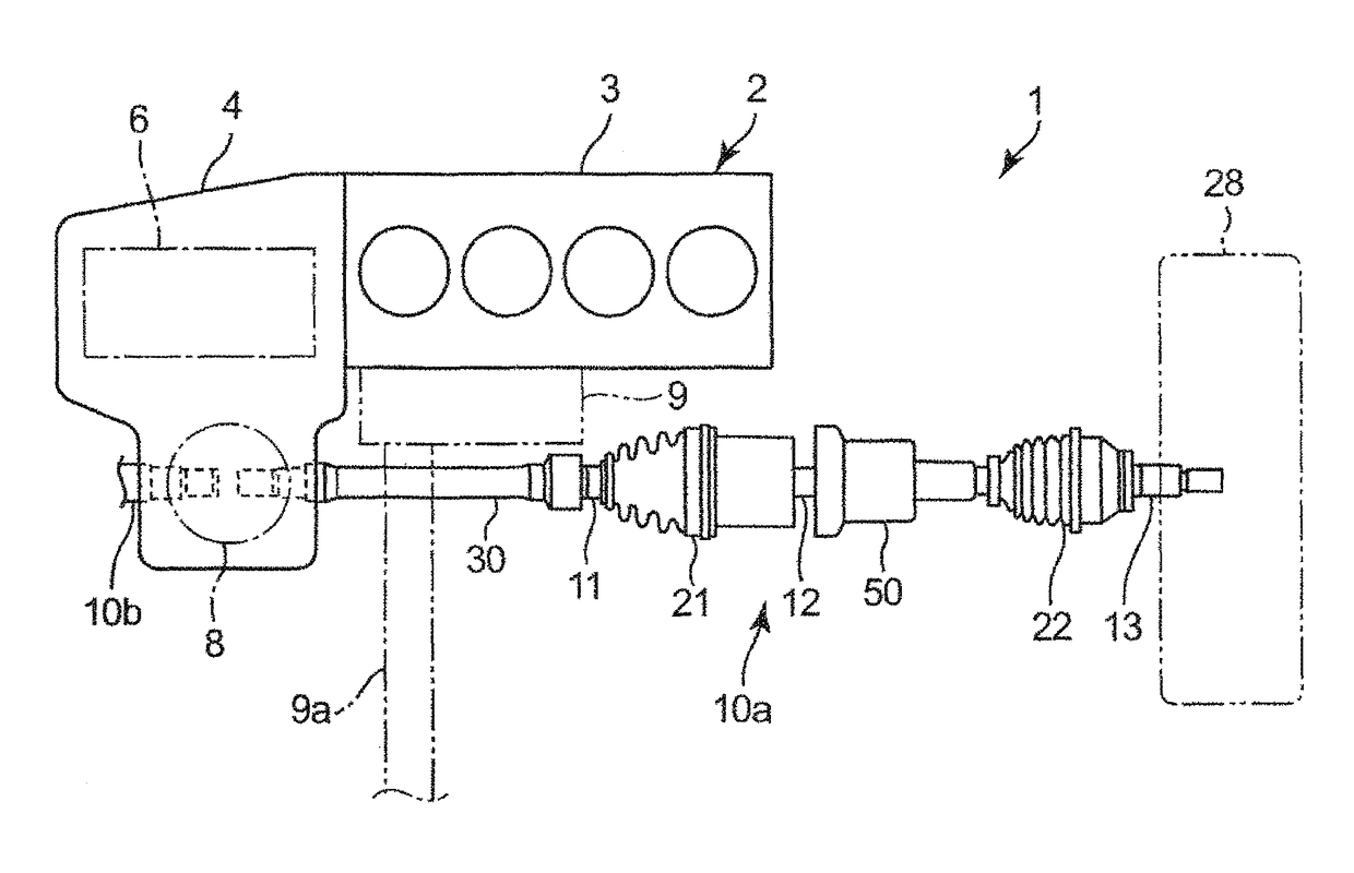
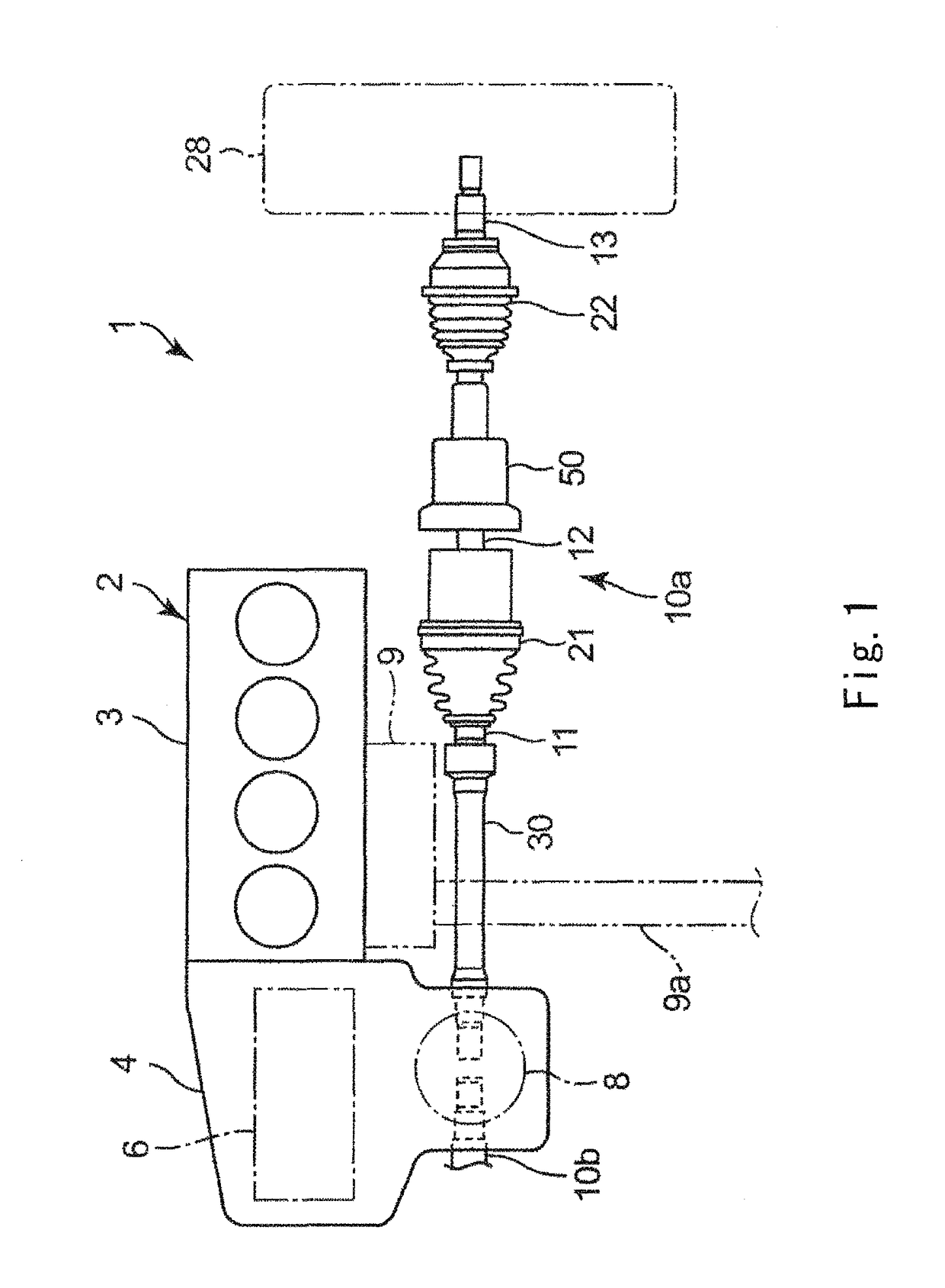
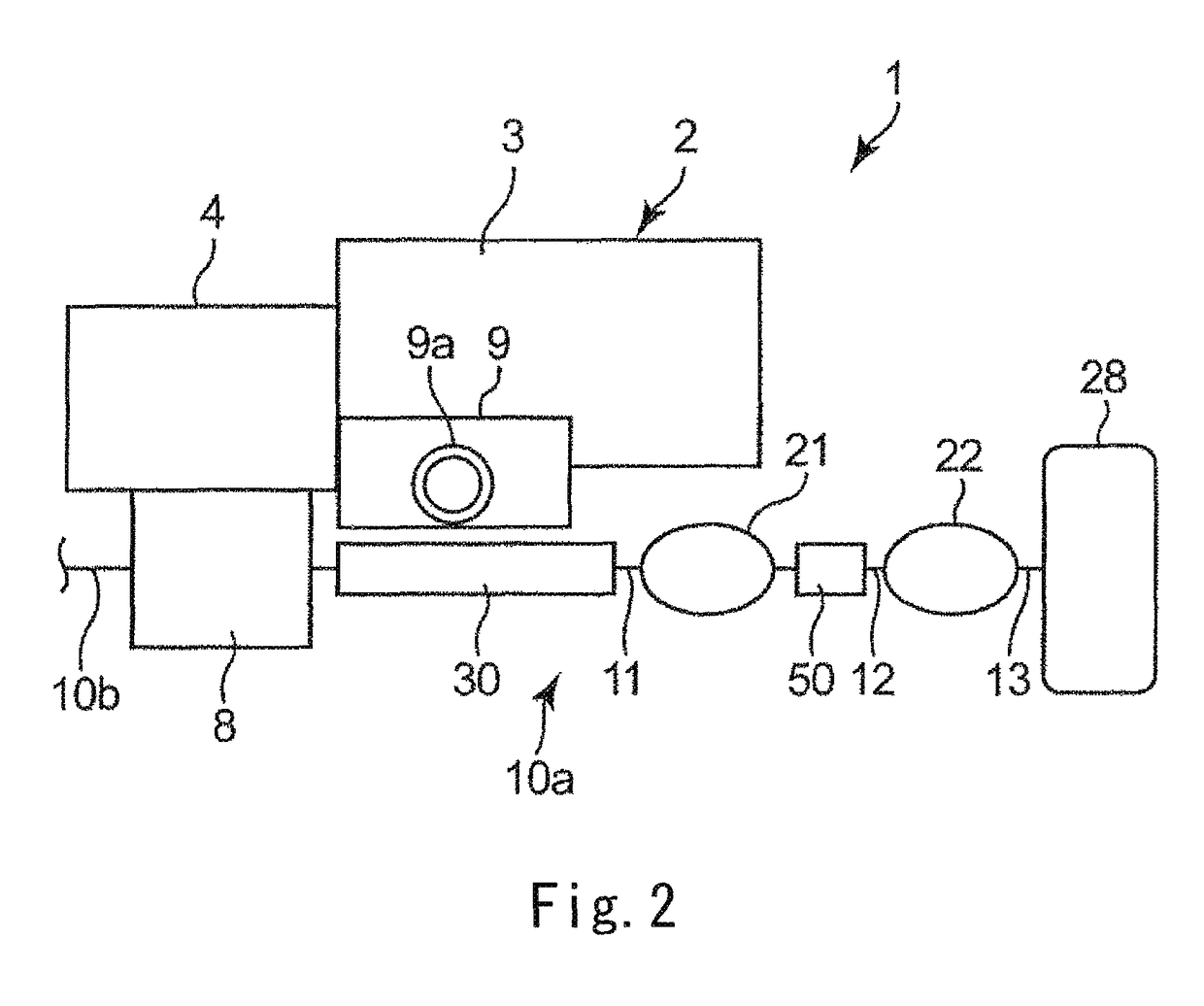
[0060]FIG. 1 is a plan view showing a power transfer device 1 of a vehicle according to Embodiment 1. FIG. 2 is a schematic diagram showing the power transfer device 1 when the power transfer device 1 is viewed from a rear side of the vehicle.

[0061]As shown in FIGS. 1 and 2, the power transfer device 1 is mounted on a front engine-front drive vehicle (FF vehicle). For example, the power transfer device 1 includes: a power source 2 mounted on an engine room; and a pair of right and left drive shafts 10 (10a and 10b) configured to couple right and left driving wheels 28 to the power source 2.

[0062]The power source 2 includes a transversely mounted type engine 3 and a transaxle 4 provided at a left side of the engine 3 in a vehicle width direction. An exhaust apparatus 9 including an exhaust pipe 9a extending rearward is connected to the engine 3. The transaxle 4 includes: a transmission 6 coupled to an output shaft of the engine 3 through, for example, a torque converter (not shown); ...

embodiment 2

[0095]Next, Embodiment 2 of the present invention will be explained in reference to FIGS. 7 to 9. In Embodiment 2, detailed explanations of the same components as in Embodiment 1 are omitted. In FIGS. 7 to 9, the same reference signs are used for components having the same functions as in Embodiment 1.

[0096]In Embodiment 2, a second high-frequency damper 80 as a third damper is provided on the drive shaft 10a in addition to the low-frequency damper 30 and the high-frequency damper 50 which are the same as those in Embodiment 1. Embodiment 2 is the same in configuration as Embodiment 1 except that the second high-frequency damper 80 is added.

[0097]As with Embodiment 1, the low-frequency damper 30 is provided on the differential-side shaft 11, and the high-frequency damper 50 (hereinafter may be referred to as a “first high-frequency damper 50”) is provided on the intermediate shaft 12. Then, the second high-frequency damper 80 is provided on the wheel-side shaft 13.

[0098]One example ...

embodiment 3

[0111]Hereinafter, Embodiments 3 to 5 of the present invention will be explained in reference to FIGS. 10 to 12. In Embodiments 3 to 5, detailed explanations of the same components as in Embodiments 1 and 2 are omitted. In FIGS. 10 to 12, the same reference signs are used for components having the same functions as in Embodiments 1 and 2.

[0112]In Embodiment 1 described above, among the differential-side shaft 11, the intermediate shaft 12, and the wheel-side shaft 13 constituting the drive shaft 10a, the dampers 30 and 50 are provided on the differential-side shaft 11 and the intermediate shaft 12, respectively. In Embodiment 2 described above, the dampers 30, 50, and 80 are provided on the shafts 11, 12, and 13, respectively. However, in the present invention, dampers are only required to be provided on at least two shafts, as in Embodiments 3 to 5 explained below, for example.

[0113]In Embodiment 3 shown in FIG. 10, the two dampers 30 and 80 are provided on the drive shaft 10a. Spe...


PUM


Abstract

In a transfer structure of a vehicle according to one aspect of the present invention, a drive shaft includes: a first power transfer shaft including a first end coupled to a differential device; a second power transfer shaft including a first end coupled to a second end of the first power transfer shaft through a first universal joint; and a third power transfer shaft including a first end coupled to a second end of the second power transfer shaft through a second universal joint and a second end to which a driving wheel is coupled, and dampers are provided on at least two respective power transfer shafts. Among these dampers, a predetermined damper arranged on the longest power transfer shaft out of the at least two power transfer shafts functions in a frequency region lower than a frequency region in which a remaining damper functions.

Description

TECHNICAL FIELD[0001]The present invention relates to a power transfer structure of a vehicle including a drive shaft on which a damper is provided. The present invention belongs to a field of a power transfer technology of vehicles.BACKGROUND ART[0002]For the purpose of improving fuel efficiency of an engine, a reduced cylinder operation may be performed in accordance with a driving state. Further, a homogeneous-charge compression ignition (HCCI) technology has been developed, in which self-ignition combustion is performed in a predetermined range in a gasoline engine. The fuel efficiency can be improved also by performing HCCI combustion.[0003]However, when the reduced cylinder operation or the HCCI combustion is performed, the combustion of the engine tends to become unstable, and vibrations by torque fluctuation or the like tend to increase. The vibrations of the engine are transferred through a transmission and a differential device to a drive shaft that couples the differentia...

Claims


Application Information

Patent Timeline
Patent Type & Authority Patents(United States)
IPC IPC(8): B60K17/30B60K17/16F16F15/12F16F15/10F16D3/223F16D3/76F16D3/68F16D3/84F16D3/227
CPCB60K17/30B60K17/165F16D3/223F16D3/68F16D3/76F16F15/12F16F15/1208F16F15/10F16D2300/22F16D3/227F16D3/845B60K5/04B60K17/22F16F15/126
Inventor NISHIMURA, KENICHIROMITO, EIJI
Owner MAZDA MOTOR CORP
Why Eureka
Try Eureka