Shaftless sealing door locking device

A door lock, shaftless technology, applied in the direction of building fasteners, wing fan fasteners, buildings, etc., can solve the problems of easy sliding of bolts, large air leakage, easy tripping, etc., and achieve reliable locking and operation. Simple, compact effects

Active Publication Date: 2015-04-22
CHENGDU KEHENG ENVIRONMENTAL PROTECTION TECH
View PDF6 Cites 0 Cited by
  • Summary
  • Abstract
  • Description
  • Claims
  • Application Information

AI Technical Summary

Problems solved by technology

These forms have some shortcomings. For example, the door buckle type is easy to release with the vibration of the equipment, the bolt type is easy to slip and buc

Method used


Image

  • Shaftless sealing door locking device
  • Shaftless sealing door locking device
  • Shaftless sealing door locking device

Examples


Embodiment Construction

[0024] Embodiments of the present invention will be further described below in conjunction with the accompanying drawings.

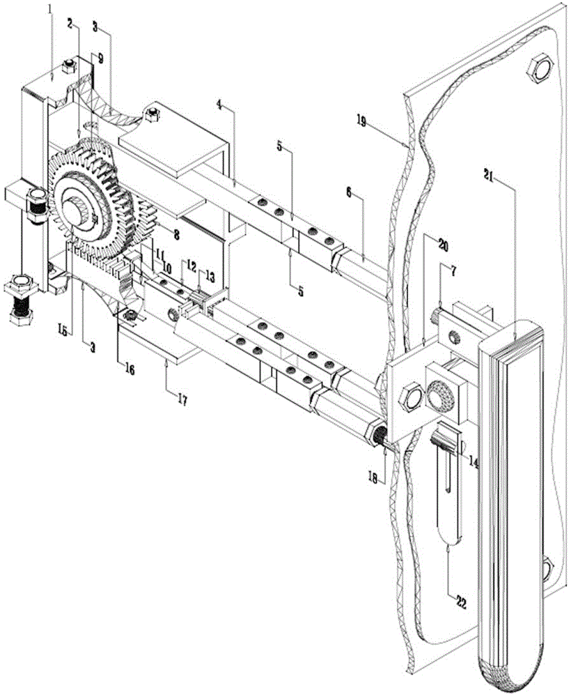
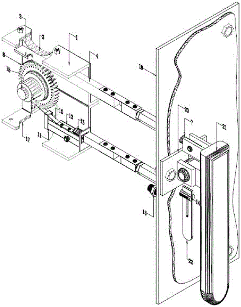
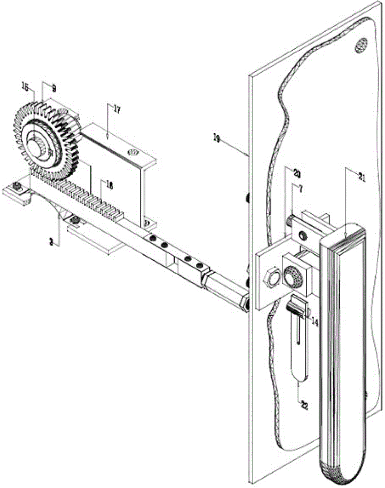
[0025] See figure 1 , a novel shaftless sealing door locking device of the present invention,

[0026] Among them, the casing part: includes the upper casing 1 and the lower casing 17; the upper casing 1 is equipped with the claw guide plate 2 and the U-shaped spring piece 3, and the claw guide plate 2 is fixedly installed in the upper casing 1; the U-shaped spring The piece is installed in the upper casing with a certain spring compression margin; the lower casing is equipped with a U-shaped spring piece 3, an unlocker 11, a non-return spring piece 10, and an unlocker bracket 12. The U-shaped spring piece is installed in the lower casing with a certain spring compression margin; the unlocker takes the pin shaft as a fulcrum and is installed in the unlocker bracket through the pin shaft. The unlocker bracket is fixedly installed in the lower casing. T...


PUM


Abstract

The invention discloses a shaftless sealing door locking device which comprises a drive wheel, a tightening wheel, a transmission shaft, a tightening handle, a machine claw, a non-return spring sheet, a tightening rack, an upper enclosure and a lower enclosure, wherein the transmission shaft is arranged in an enclosure formed by the upper enclosure and the lower enclosure; the drive wheel and the tightening wheel are arranged on the transmission shaft; the tightening handle is arranged on a fixed base through a shaft, the upper end of the tightening handle is connected with the machine claw, and the machine claw is engaged with the drive wheel; the fixed base is fixed on a door; one end of the tightening rack is engaged with the tightening wheel, and the other end of the tightening rack is fixedly connected with the door; one end of the non-return spring sheet is fixed on the enclosure, the other end of the non-return spring sheet can be inserted into the drive wheel when the drive wheel reversely rotates to prevent the drive wheel from reversely rotating. The shaftless sealing door locking device disclosed by the invention has the benefits of compact structure, easiness in operation, reliability in locking, and no maintenance after repeated use; the sealing effect of the door is improved while the great convenience is brought to the repair and the maintenance of a harmful gas absorbing device.

Description


Claims


Application Information

Patent Timeline
Owner CHENGDU KEHENG ENVIRONMENTAL PROTECTION TECH
Why Eureka
Try Eureka