Engine exhaust pipeline structure

An exhaust pipeline and engine technology, which is applied in the direction of engine components, machines/engines, exhaust devices, etc., can solve the problems of high degree of integration of exhaust pipelines, difficulty in casting or welding, and high failure rate of products. Achieve the effects of improving the exhaust effect, increasing the casting pass rate, and reducing the difficulty of casting

Inactive Publication Date: 2015-04-22
CHONGQING PUSH MECHANISM
View PDF2 Cites 1 Cited by
  • Summary
  • Abstract
  • Description
  • Claims
  • Application Information

AI Technical Summary

Problems solved by technology

Both of the above two patents are made of integral casting or welding, the exhaust pipeline is highly integrated, the structure is complex, casting or welding is difficult, and the product failure rate is high.

Method used


Image

  • Engine exhaust pipeline structure

Examples


Embodiment Construction

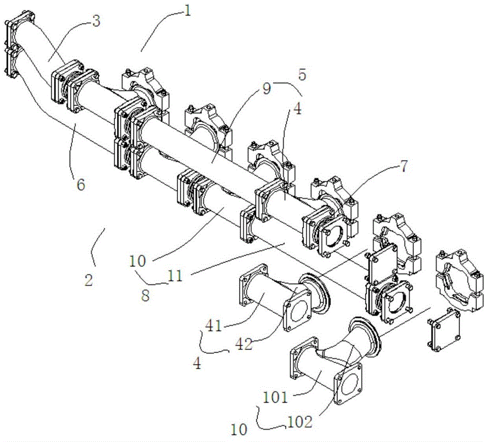
[0014] The present invention will be further described below in conjunction with the embodiments and accompanying drawings.

[0015] Such as figure 1 The engine exhaust pipeline structure shown includes a first exhaust pipe 1 and a second exhaust pipe 2 arranged side by side, and the first exhaust pipe 1 is composed of a first inlet pipe 3 and a first module pipe 4 and at least one first pipe group 5 connected sequentially, the first pipe group 5 is formed by sequentially connecting the first connecting pipe 9 and the two first modular pipes 4, and the second exhaust pipe 2 is formed by The second inlet pipe 6 and at least one second pipe group 8 are sequentially connected, and the second pipe group 8 is formed by sequentially connecting two second modular pipes 10 and the second connecting pipe 11. The second modular pipe 10 is arranged correspondingly to the first connecting pipe 9, and the second connecting pipe 11 is arranged correspondingly to the two first modular pipes...


PUM


Abstract

The invention discloses an engine exhaust pipeline structure. The engine exhaust pipeline structure comprises a first exhaust pipe and a second exhaust pipe which are arranged side by side. The first exhaust pipe is formed by connecting a first inlet pipe, first module pipes and at least one first pipe set in sequence. The second exhaust pipe is formed by connecting a second inlet pipe and at least one second pipe set in sequence. The first inlet pipe, the first module pipe and the second inlet pipe are correspondingly arranged. The first pipe set and the second pipe set are correspondingly arranged. By means of the structure, the modular design is carried out on the first exhaust pipe and the second exhaust pipe, a segmented arrangement form of various cylinder exhaust pipes is presented, and the engine exhaust pipeline structure is simpler, more reasonable and more attractive in appearance. Meanwhile, the casting difficulty can be obviously lowered through the modular design of the cylinder exhaust pipes, the exhaust pipeline transition is smoother, the yield of castings is increased, and the assembling technology is improved.

Description

technical field [0001] The invention belongs to the technical field of engines, and in particular relates to an engine exhaust pipeline structure. Background technique [0002] Exhaust gas turbocharging exhaust method is the most commonly used supercharging method for engines at present. However, due to the number of engine cylinders, ignition sequence and different applications, the exhaust gas turbocharging arrangement is often divided into constant pressure turbocharging and pulse turbocharging. pressure. At present, most marine engines are actually used in low-speed and low-load conditions for a long time, and under this condition, the exhaust energy of the engine is small, the speed of the turbocharger is low, and the acceleration response is poor, resulting in the engine under this condition. Lower torque. However, for most marine engines, it is very necessary to increase the low-speed high torque, and the reasonable design of the exhaust system is one of the effecti...

Claims


Application Information

Patent Timeline
Patent Type & Authority Applications(China)
IPC IPC(8): F01N13/08F01N13/18
Inventor 龙金
Owner CHONGQING PUSH MECHANISM
Why Eureka
Try Eureka