Bucket cylinder

A technology for oil cylinders and buckets, applied in the field of oil cylinder development, can solve the problems of increased processing difficulty, poor buffering effect, and difficult processing of parts, etc., and achieve the effects of low coaxiality requirements, easy processing, and good buffering effect

A technology for oil cylinders and buckets, applied in the field of oil cylinder development, can solve the problems of increased processing difficulty, poor buffering effect, and difficult processing of parts, etc., and achieve the effects of low coaxiality requirements, easy processing, and good buffering effect

CN104533874AInactive Publication Date: 2015-04-22CSIC ZHONGNAN EQUIP

Image

  • Bucket cylinder
  • Bucket cylinder
  • Bucket cylinder

Examples


Embodiment Construction

[0027] The present invention will be described in detail below with reference to the accompanying drawings and examples.

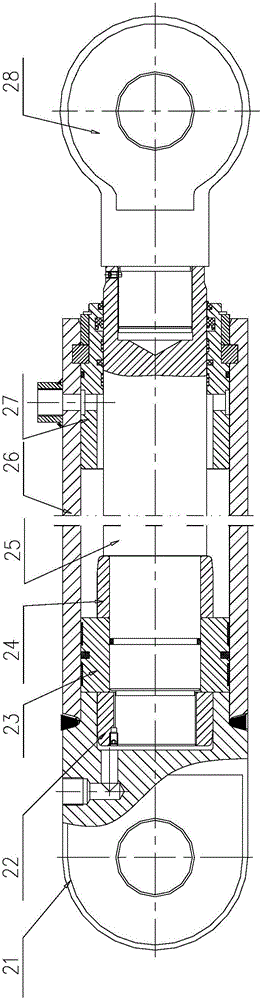
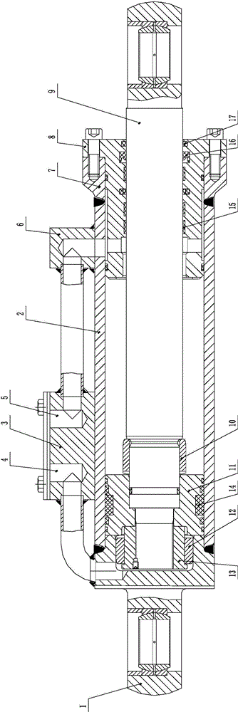
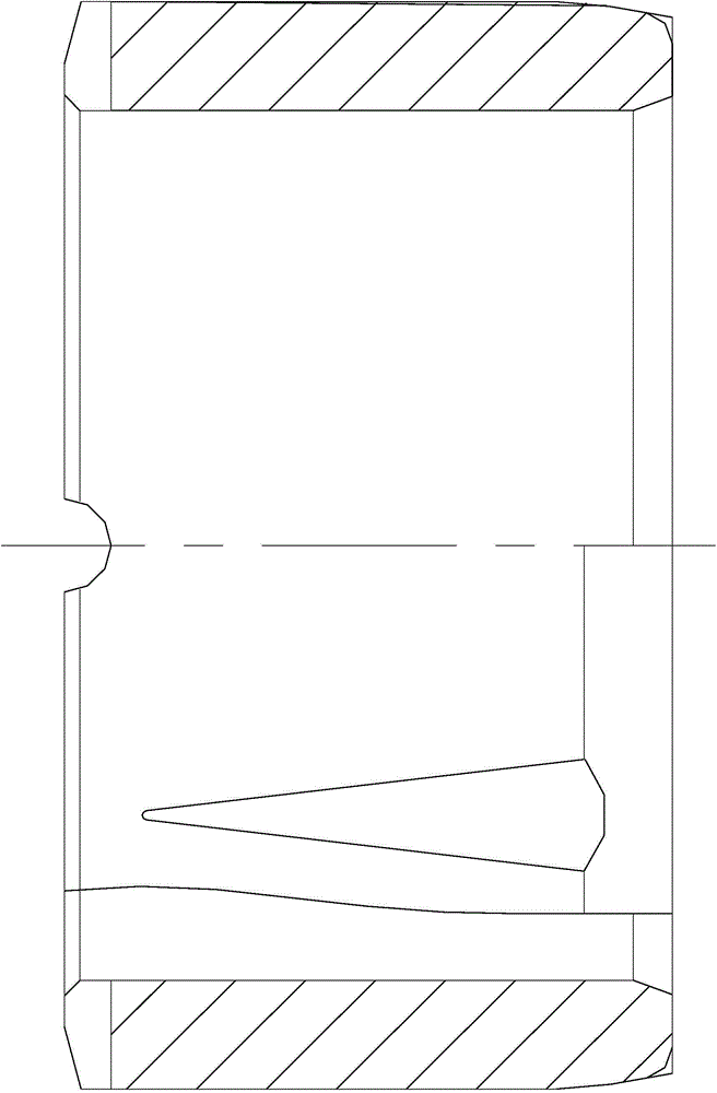
[0028] For the cylinder assembly, refer to the attached figure 2 , including: cylinder bottom 1, cylinder barrel 2, valve seat 3, bend through 6, cylinder head 7, guide sleeve 8, guide ring 15, rod seal 16 and dust seal 17; see attached Figure 5 , 6, the cylinder bottom 1 is divided into a cylindrical part and a connecting head part, a blind hole is opened along the axial direction of the cylindrical part, and a radial through hole connected with the blind hole is provided along the peripheral surface of the cylindrical part; the cylinder barrel 2 It is a cylinder with an axial through hole, and a radial through hole connected with the axial through hole is provided on the peripheral surface of the cylinder; the valve seat 3 is provided with two L-shaped through holes, which are oil holes respectively. A4 and oil hole B5; the bend 6 is provided with an...


PUM


Abstract

The invention discloses a bucket cylinder, and belongs to the technical field of oil cylinder development. The bucket cylinder comprises a cylinder component and a piston component, wherein the piston component sleeves the inner circumferential surface of the cylinder component; a piston rod of the piston component is adhered to the inner circumferential surface of a small circular inner diameter part of a guide sleeve of the cylinder component; an annular gap is formed between the piston rod and the inner circumferential surface of the large circular inner diameter part of the guide sleeve; the piston of the piston component is adhered to the inner circumferential surface of the cylinder of the cylinder component; the piston rod, a screw nut and a rear buffer sleeve of the piston component, and the cylinder bottom of the cylinder component form a rear buffer; a front buffer sleeve, the piston and the piston rod of the piston component and the and the guide sleeve of the cylinder component form a front buffer. Due to automatic flotation centering of the front buffer sleeve and the rear buffer sleeve, a good buffer effect is achieved, the requirement on the coaxiality of components is low, and the components are easy to process.

Description

technical field [0001] The invention belongs to the technical field of oil cylinder development, and in particular relates to a bucket oil cylinder. Background technique [0002] Backhoe loader is a widely used multifunctional construction machinery. Because it can quickly replace a variety of operating devices and varieties, high quality and high efficiency, it is favored by the majority of construction units, and its manufacturing industry is also booming; In the process, the speed is fast, the efficiency is high, the maneuverability is good, and the operation is easy; at the same time, when the cylinder moves to the fully extended end and fully retracted end, it is required to run smoothly and withstand shocks, that is, the cylinder is required to be cushioned before and after. [0003] For the existing fixed buffer cylinder structure, please refer to the attached figure 1 , including: cylinder head B21, rear buffer sleeve B22, piston B23, front buffer sleeve B24, pisto...

Claims


Application Information

Patent Timeline
22 Apr 2015
Publication
CN104533874A
IPC
F15B15/14; F15B15/22; F15B15/20
CPC
F15B15/14; F15B15/1457; F15B15/227
Inventors
ζ–½ζˆ˜ε†›; 刘建魁