Dynamic pressure balance rotary sealing part
A rotary seal and dynamic pressure balance technology, applied in the field of high-pressure high-speed rotary seals, rotary seals, can solve the problems of poor adaptability and followability, and achieve the effects of strong designability, good sealing reliability, and long service life
- Summary
- Abstract
- Description
- Claims
- Application Information
AI Technical Summary
Problems solved by technology
Method used
Image
Examples
Embodiment 1
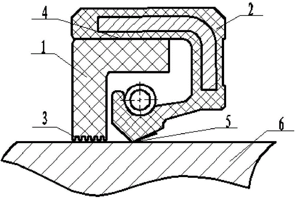
[0032] An integrally assembled dynamic pressure balanced rotary seal, the structure of which is shown in Appendix 1.
[0033] The specification of the oil seal is Φ90-120-12, and the lip is designed with a return line.
[0034] The assembly width of the rigid sealing ring is 7mm; the outer diameter of the rigid sealing ring is an interference fit with the inner side of the oil seal 4; the sealing surface of the rigid sealing ring is a rectangular return groove, the width of the sealing surface is 3mm, the gap between the rigid sealing ring and the rotating shaft is 0.05mm, and the helix angle is 2° , Spiral groove depth 1.0mm.
[0035] The rigid sealing ring 1 and the rubber oil seal 2 are assembled into one body to obtain the sealing member involved in the present invention.
[0036] Under the conditions of sealing pressure of 1.2MPa and rotating linear speed of 20m / s, the seal has no leakage in 48 hours of test assessment.
[0037] If the same type of oil seal is used alon...
Embodiment 2
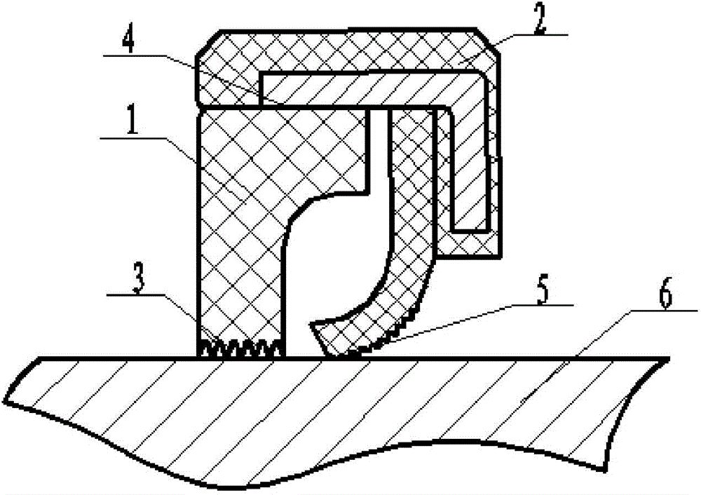
[0039] An integrally assembled dynamic pressure balanced rotary seal, the structure is as attached figure 2 shown.
[0040] The specification of the oil seal is Φ90-120-12, and the lip is designed with a return line.
[0041] The assembly width of the rigid seal ring is 6mm; the outer diameter of the rigid seal ring is an interference fit with the inside of the oil seal frame; the sealing surface of the rigid seal ring is a rectangular return groove, the width of the seal surface is 4mm, the gap between the rigid seal ring and the rotating shaft is 0.1mm, and the helix angle 15°, spiral groove depth 0.8mm.
[0042] The rigid sealing ring 1 is assembled with the polytetrafluoroethylene oil seal 2 to obtain the sealing member of the present invention.
[0043] The seal has no leakage for 48 hours at a sealing pressure of 0.3MPa and a rotational speed of 40m / s.
Embodiment 3
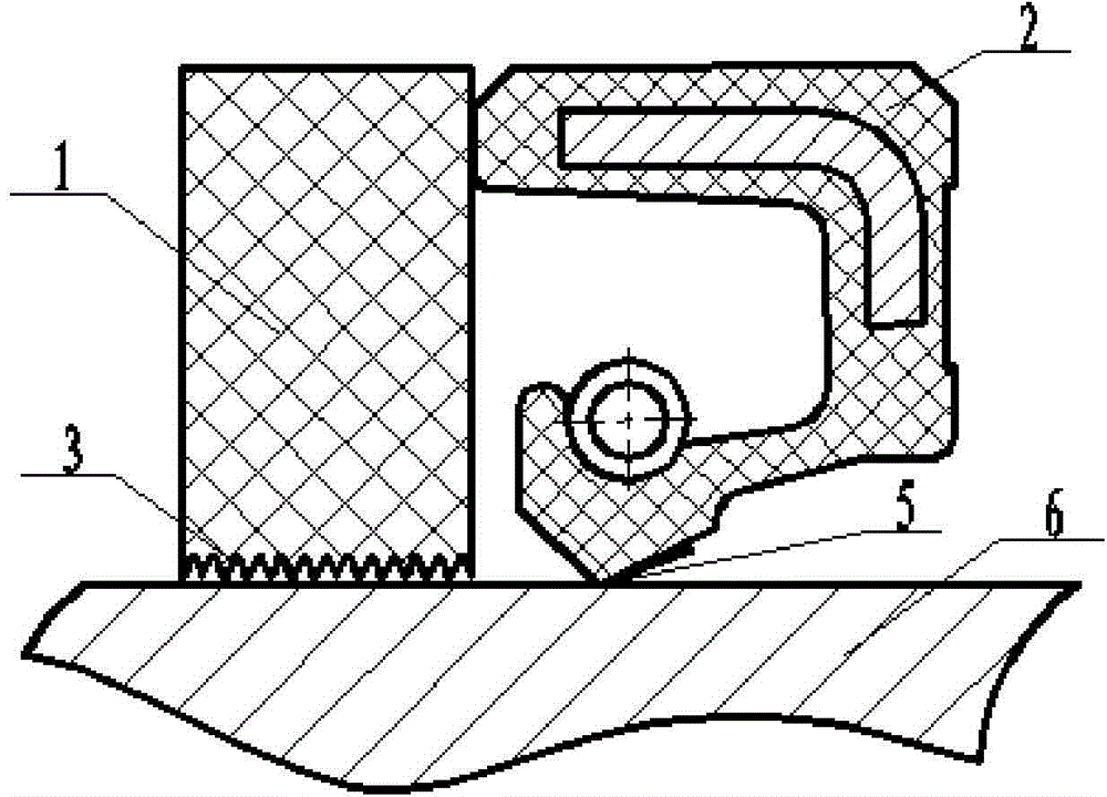
[0045] An assembled dynamic pressure balanced rotary seal, the structure is as attached image 3 shown.
[0046] The specification of the oil seal is Φ170-200-15, and the lip is designed with a return line.
[0047] The outer diameter of the rigid sealing ring is the same as the inner diameter of the cavity; the sealing surface of the rigid sealing ring is a rectangular return groove, and the width of the sealing surface of the rigid sealing ring is 10mm; the gap between the rigid sealing ring and the rotating shaft is 0.5mm, the helix angle is 20°, and the helical groove is deep 0.2mm.
[0048] The rigid sealing ring 1 and the rubber oil seal 2 are assembled into one body to obtain the sealing member involved in the present invention.
[0049] The seal has no leakage for 48 hours at a sealing pressure of 0.5MPa and a rotational speed of 20m / s.
PUM
| Property | Measurement | Unit |
|---|---|---|
| Helix angle | aaaaa | aaaaa |
| Depth | aaaaa | aaaaa |
| Width | aaaaa | aaaaa |
Abstract
Description
Claims
Application Information
 - R&D
- Intellectual Property
- Life Sciences
- Materials
- Tech Scout
- Unparalleled Data Quality
- Higher Quality Content
- 60% Fewer Hallucinations
Browse by: Latest US Patents, China's latest patents, Technical Efficacy Thesaurus, Application Domain, Technology Topic, Popular Technical Reports.
© 2025 PatSnap. All rights reserved.Legal|Privacy policy|Modern Slavery Act Transparency Statement|Sitemap|About US| Contact US: help@patsnap.com


