
Visible light signal transceiver

A signal transceiver and optical signal technology, applied in electromagnetic transceivers, short-range systems, free space transmission, etc., can solve the problems of high installation position and installation angle, signal strength influence, etc., to reduce difficulty and improve signal Strength, the effect of improving usability

Inactive Publication Date: 2015-04-22
FUDAN UNIV
View PDF3 Cites 9 Cited by
  • Summary
  • Abstract
  • Description
  • Claims
  • Application Information

AI Technical Summary

Problems solved by technology

[0004] However, when the existing visible light signal transceiver device receives or transmits visible light signals, due to its own structural limitations, the visible light signal transceiver device can only transmit and receive visible light signals within a specified angle, so that the staff are installing it. When using the visible light signal transceiving device, it is necessary to consider the signal receiving and sending angle of the visible light signal transceiving device to ensure that the visible light signal sent by the transmitter can be received by the receiver. High, once the position is shifted during installation, it will affect the strength of the signal

Method used


Image

  • Visible light signal transceiver
  • Visible light signal transceiver
  • Visible light signal transceiver

Examples


Embodiment Construction

[0024] In order to make the object, technical solution and advantages of the present invention clearer, various embodiments of the present invention will be described in detail below in conjunction with the accompanying drawings. However, those of ordinary skill in the art can understand that, in each implementation manner of the present invention, many technical details are provided for readers to better understand the present application. However, even without these technical details and various changes and modifications based on the following implementation modes, the technical solution claimed in each claim of the present application can be realized.

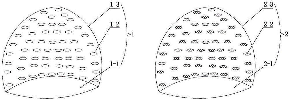
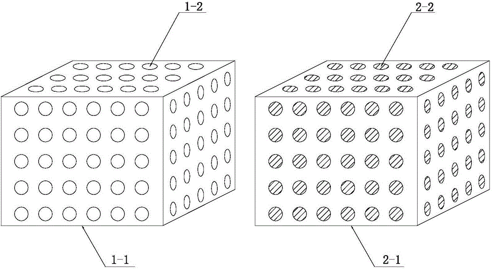
[0025] The first embodiment of the present invention relates to a visible light signal transceiving device, such as figure 1 As shown, it includes a light emitting unit 1 emitting visible light signals and a light receiving unit 2 receiving visible light signals.

[0026] Wherein, the light emitting unit 1 has an optical si...


PUM


Abstract

The invention relates to a visible light signal transceiver, which comprises a light emitting unit capable of emitting a visible light signal and a light receiving unit capable of receiving the visible light signal, wherein the light emitting unit is provided with a light signal emission surface for emitting the visible light signal, and the light receiving unit is provided with a light signal receiving surface for receiving the visible light signal emitted by the light emitting unit. In comparison with the prior art, the light emitting unit and the light receiving unit are capable of emitting and receiving the visible light signal through the forms of the light emitting surface and the light receiving surface respectively, so that the signal intensity of the visible light signal transceiver during communication is improved through increasing the areas of the light emitting unit and the light receiving unit when emitting and receiving the visible light signal.

Description

technical field [0001] The invention relates to a wireless signal transceiving device, in particular to a visible light signal transceiving device. Background technique [0002] Visible Light Communication technology (Visible Light Communication, VLC) refers to a communication method that uses light in the visible light band as an information carrier and directly transmits optical signals in the air without using optical fiber and other wired channel transmission media. [0003] At present, common visible light signal transceiver devices generally use visible light light-emitting diodes, that is, LEDs as illuminants. Compared with fluorescent lamps and incandescent lamps, LEDs have faster switching speeds, and use large indoor and outdoor display screens equipped with LEDs, lighting equipment, The information is modulated and transmitted by high-speed modulated light wave signals that are invisible to the naked eye, and then photoelectric conversion devices such as photodiod...

Claims


Application Information

Patent Timeline
Patent Type & Authority Applications(China)
IPC IPC(8): H04B10/40H04B10/116
Inventor 迟楠
Owner FUDAN UNIV
Learn More