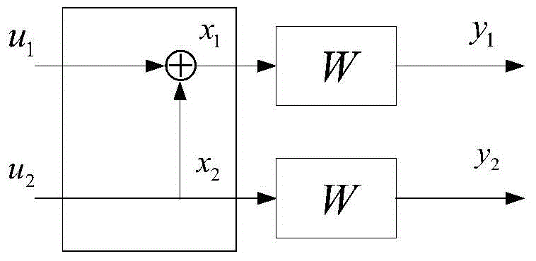
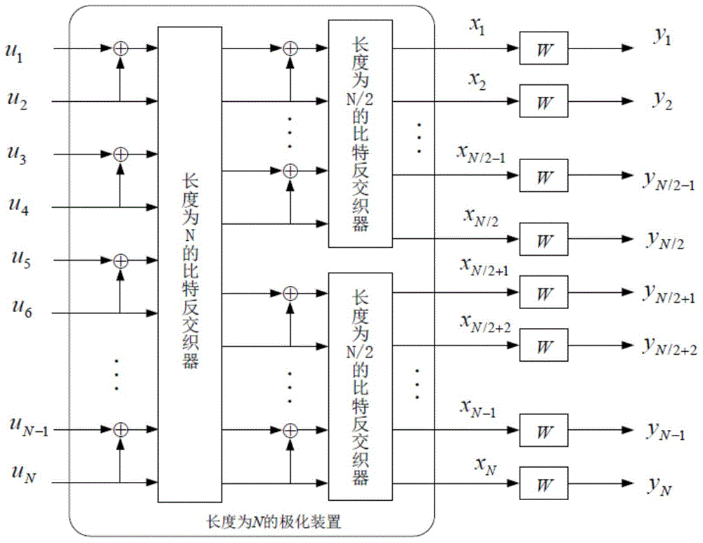
[0029] In order to make the objectives, technical solutions and advantages of the present invention clearer, the implementation process and performance analysis of the present invention will be further described in detail below in conjunction with the accompanying drawings and simulation examples.
[0030] See Figure 4 , Introduce the source coding method based on polarization code of the present invention:
[0031] First determine the symbol value set of the source recovery signal, and then use the best symbol-to-bit mapping rule to serially map the source symbol sequence into a bit soft information sequence, and perform polarization coding on the bit soft information sequence The serial offset coding is to find the coding path with the largest reliability value and the bit sequence corresponding to the coding path, and finally through the reliable bit set, select the most important part of the bits from the bit sequence as the coding result.
[0032] See Figure 5 , Specifically introduce the following operation steps of the method of the present invention:
[0033] Step 1. Determine the parameters of the source coding method: quantize the source symbol sequence with a sequence length of N by R bits, that is, represent each source symbol as R bits on average; then set the polarization code serial offset coding separately The number of devices is m, the path length of each polarization code serial cancellation coding device is N, and the search width of the polarization code serial cancellation coding device is L; where R is an integer and a decimal greater than zero, N , M and L are all positive integers, and m>R.
[0034] In step 1, when the search width L=1, the operation of the polarization code serial cancellation encoding method is the simplest, with only one encoding path.
[0035] Step 2. Construct the structure of the polarization code serial cancellation coding device: construct a list of 2×L path records for each serial cancellation coding device, and each path record in the list is used to store a maximum length. Is the N bit sequence and its corresponding reliability value.
[0036] Step 3. Use the uniform quantization method or the best scalar quantization method to generate the symbol value set of the source recovery signal The number of symbols in the symbol value set is 2 m; For a Gaussian distributed signal source, the geometric Gaussian quantization method is used to generate the symbol value set of the source recovery signal;
[0037] In this step 3, before the uniform quantization method or the best scalar quantization method is used to generate the symbol value set of the source recovery signal, two arrays need to be initialized: one is marked with a size of 2. m The quantization level array of the quantization level array is marked as the quantization level value; the other is marked as the size (2 m +1) layered level array, the elements of the layered level array are recorded as layered level values.
[0038] After completing the initial setting operation, perform the following operations:
[0039] If the uniform quantization method is used to generate the symbol value set of the source recovery signal, the following operation steps are included:
[0040] (3A) Obtain the minimum and maximum values of the source signal distribution, and assign them to the first layer level and the last layer level of the layer level array respectively;
[0041] (3B) Divide the symbol value interval of the source signal into equally spaced 2 m Subintervals
[0042] (3C) The value of the lth layer level is selected as the sum of the (l-1)th layer level value and the subinterval size, and the lth layer level value is compared with the ) The average value of the hierarchical level values is used as the value of the (l-1)th quantization level; where the hierarchical level number l is a natural number not less than 2;
[0043] (3D) Determine whether to complete the second m Calculate a quantization level value. If yes, perform the following step (3E); otherwise, add 1 to the value of the layered level number l, and return to step (3C);
[0044] (3E) Use the finally obtained quantization level value as the symbol value of the source recovery signal, and form the symbol value set of the recovery signal So far, all operation steps of the uniform quantization method are completed.
[0045] If the best scalar quantization method is used to generate the symbol value set of the source recovery signal, the following steps are included:
[0046] (3a) Select part of the data from the source symbol sequence as training samples, and the number of training samples is not less than 1000;
[0047] (3b) In the t-th operation process, the quantized level value obtained in the (t-1)-th operation process is subjected to adjacent pairwise average calculation operations, and each average value is obtained as the t-th operation process The hierarchical level value of; where the number of operations t is a natural number not less than 2;
[0048] (3c) Allocate the training samples to the corresponding hierarchical level interval in order according to the value size, then calculate the average value of all training samples whose values are in the same interval, and use the average value as the tth operation to get Then, quantize all training samples with values in the same interval to the same quantization level value, and calculate the quantization noise of the source sequence during the tth operation;
[0049] (3d) Determine whether the obtained quantization noise is less than the pre-set threshold, if yes, perform the following step (3e); otherwise, add 1 to the number of operations t and return to step (3b);
[0050] (3e) Use the finally obtained quantization level value as the symbol value of the source recovery signal, and form the symbol value set of the recovery signal So far, all the steps of the optimal scalar quantization method have been completed.
[0051] However, in step 3, for the mean is μ and the variance is δ 2 For the Gaussian distributed information source, the geometric Gaussian quantization method is used to generate the symbol value set of the source recovery signal. The method includes the following operations:
[0052] (31) Calculate the inverse function of the rate-distortion function R(D) of the Gaussian distribution source to obtain the distortion value D, and set the first layer level value to be a real number close to negative infinity;
[0053] (32) Taking the (l-1)th stratification level value as the lower limit of integration, the mean value is μ and the variance is (δ 2 -D) Gaussian function to integrate; until a certain upper limit of the integral makes the integral value 1/2 m Stop the integration operation, and use the value of the upper limit of the integration as the (l-1)th element of the layered level array; then, calculate the value from the (l-1)th layered level and the lth The average value in the layer level interval composed of the layer level values, and use the average value as the (l-1)th quantization level value of the quantization level array;
[0054] (33) Determine whether to complete the second m The calculation operation of a quantization level value, if yes, execute the following step (34); otherwise, add 1 to the value of the layered level number l, and return to execute step (32);
[0055] (34) Use the finally obtained quantization level as the symbol value of the source recovery signal, and form the symbol value set of the recovery signal
[0056] Step 4. Optimize the symbol-to-bit mapping rule and determine the reliable bit set.
[0057] In step 4, include the following operations:
[0058] (4A) First define the one-to-one mapping rule from symbol to bit as: Where Is the symbol value set of the source recovery signal, Is the m bits that constitute the symbol of the source recovery signal, namely (b 1 ,...,b m ); redefine 2 m The binary input channel is The symbol value set of the input signal is the symbol value set of the source recovery signal, the symbol value set of the output signal is the value set of the source symbol, and the transition probability function obeys the mean value The sum variance is (δ 2 -D) Gaussian function of the distribution;
[0059] (4B) Then randomly set a symbol-to-bit mapping rule
[0060] (4C) Calculation 2 m Base channel Kth bit subchannel Channel capacity In the formula, the natural number k is the sequence number of the bit sub-channel, and its maximum value is m; the input of the k-th bit sub-channel is b k ∈{0,1}, the output is the source symbol and the first (k-1) bits, {0,1} k-1 Represents the (k-1) Cartesian product of {0,1};
[0061] (4D) The k-th bit subchannel is equivalent to a binary input Gaussian channel with equal capacity, and the transition probability distribution of the Gaussian channel is obtained;
[0062] (4E) Pair N 2 m Base channel The k-th bit subchannel Perform a polarization operation to obtain N polarization bit channels;
[0063] (4F) Use Gaussian approximation method to obtain the error probability of N polarization bit channels, and then judge and calculate the channel capacity Whether the sequence number of the bit subchannel reaches its maximum value m; if so, perform the following step (4G); otherwise, add 1 to the value of the bit subchannel sequence number k and return to step (4C);
[0064] (4G) Sort the error probabilities of all mN polarized bit channels according to the numerical value, and then mark the RN bit subchannels with the smallest error probability value as a reliable bit set, and mark the remaining bit subchannels as a fixed set ;
[0065] (4H) Perform a summation operation on the elements in the reliable bit set, and determine whether the value of the operation result is the global minimum value, if so, perform the subsequent step (4I); otherwise, return to the step (4B);
[0066] (4I) Take the symbol-to-bit mapping rule corresponding to the global minimum as the optimal mapping rule, and record the corresponding reliable bit set and fixed set.
[0067] Step 5: According to the optimal symbol-to-bit mapping rule, the source symbol sequence is serially mapped into multiple layers to map the i-th layer bit soft information sequence. In the formula, the natural number i is the layer order number of the bit soft information sequence, and its maximum value is m.
[0068] In step 5, use the optimal symbol-to-bit mapping rule to serially perform multi-layer mapping of the source symbol sequence. When mapping into the i-th layer bit soft information sequence, the participation of the first (i-1) layer bits is required ; This step 5 includes the following operations:
[0069] (5A) According to the formula L i ( s ) = In ( Pr { b s , i = 1 } Pr { b s , i = 0 } ) = In ( X b s , i + 1 m A { 0,1 } m - i p ( y s | b s , 1 i - 1 , b s , i = 1 , b s , i + 1 m ) X b s , i + 1 m A { 0,1 } m - i p ( y s | b s , 1 i - 1 , b s , i = 0 , b s , i + 1 m ) ) Calculate the i-th bit b in the s-th symbol of the source symbol sequence s,i The log likelihood ratio of L i (s); where, the natural number s is the symbol number in the source symbol sequence, and its maximum value is N; In() is the operation symbol of the natural logarithm function, Pr{b s,i = 1} is the probability that the i-th bit in the s-th source symbol takes the value 1, the mean is x and the variance is (δ 2 -D) Gaussian function And x is uniquely related to Correspond to each other, Is the bit sequence composed of the i-th to m-th bits in the s-th symbol (b s,i ,...,b s,m );
[0070] (5B) Determine whether the calculation operation of the i-th bit likelihood ratio of the N-th source symbol is completed; if so, perform the following step (5C); otherwise, add 1 to the value of the symbol number s in the source symbol sequence, And return to step (5A);
[0071] (5C) The likelihood ratios of all the bits of the i-th layer form the bit soft information sequence of the i-th layer, and are sent to the i-th polarization code serial cancellation coding device for coding.
[0072] Step 6. Send the i-th layer bit soft information sequence to the i-th polarization code serial cancellation device for encoding. After the serial cancellation encoding operation is completed, it is judged whether the sequence number i of the polarization code reaches its maximum value m; , Then perform the following step 7; otherwise, add 1 to the value of the sequence number i of the polarization code, and return to step 5.
[0073] Step 6 Before performing polarization code serial cancellation encoding on the i-th layer bit soft information sequence, first set up the following encoding device structure: each serial cancellation encoding device corresponds to a binary tree encoding code tree of depth N, and define nodes The depth of is the number of non-repetitive branches experienced from the root node to the current node, that is, the depth of the root node is zero; except for leaf nodes with depth N, each node starting from the root node has two successor nodes, And mark the two branches as bit 0 and bit 1 accordingly; from the root node to the node with the current depth of j, all the branches experienced in sequence are combined into an encoding path with an encoding length of j, and the encoding path corresponds to Branch markers are combined into coded bit estimation sequence In the formula, the natural number j is the depth of the node or the length of the coding path, and the maximum value is N.
[0074] Step 6: After completing the configuration of the encoding device, perform the following encoding operations:
[0075] (6A) The reliability value of the coding path obtained by the (i-1)th polarization code serial cancellation coding device is used as the initial path reliability value of the i-th coding device; where, when i=1, the initial path The reliability value is zero;
[0076] (6B) Expand the node with depth (j-1) to obtain twice the number of new coded paths, and then use the natural number T to express the number of new coded paths; where T is the number of new coded paths , The maximum value is 2L; then according to the formula M ( u ^ 1 j | y 1 N ) = In ( W N ( j ) ( y 1 N , u 1 j - 1 = u ^ 1 j - 1 | u j = u ^ j ) X v 1 j W N ( j ) ( y 1 N , u 1 j - 1 = v 1 j - 1 | u j = v j ) ) Calculate the reliability value of each coded new path; where, Represents the transition probability function of the polarization channel corresponding to the node with depth j; the calculation method of the reliability value of the coding path is as follows:
[0077] When j is in a fixed set, The corresponding code bit is 0.
[0078] When j is in the set of reliable bits and is an odd number, let j=2z-1, then
[0079] M N ( 2 z - 1 ) ( u ^ 1 2 z - 1 | y 1 N ) = max * { M N / 2 ( z ) ( u ^ 1 , o 2 z - 2 ⊕ u ^ 1 , e 2 z - 2 , u ^ 2 z - 1 ⊕0| y 1 N / 2 ) + M N / 2 ( z ) ( u ^ 1 , e 2 z - 2 , u ^ 2 z = 0 | y N / 2 + 1 N ) , M N / 2 ( z ) ( u ^ 1 , o 2 z - 2 ⊕ u ^ 1 , e 2 z - 2 , u ^ 2 z - 1 ⊕ 1 | y 1 N / 2 ) + M N / 2 ( z ) ( u ^ 1 , e 2 z - 2 , u ^ 2 z = 1 | y N / 2 + 1 N ) } .
[0080] When j is in the set of reliable bits and is an even number, let j=2z, then
[0081] M N ( 2 z ) ( u ^ 1 2 z | y 1 N ) = M N / 2 ( z ) ( u ^ 1 , o 2 z ⊕ u ^ 1 , e 2 z | y 1 N / 2 ) + M N / 2 ( z ) ( u ^ 1 , e 2 z | y N / 2 + 1 N ) .
[0082] Where max * = ( x 1 , x 2 ) = In ( e x 1 + e x 2 ) = max ( x 1 , x 2 ) + In ( 1 + e - | x 1 - x 2 | ) ; Calculate max * (x 1 ,x 2 ) Requires multiple computing resources, so set The value of the calculation result is stored in the lookup table for calculation of max * (x 1 ,x 2 ), when Check the meter directly; Is the modulo two plus operation symbol, Represents the modulo two addition operation to these two element sequences, namely Represents u subscripted by odd numbers i Sequence of elements, Represents u subscripted by an even number i The sequence of elements that make up.
[0083] (6C) Determine whether the currently calculated number T of new encoded paths is less than the set search width L, if so, store the reliability values of all encoded new paths and the bit estimation sequence corresponding to the new path into the polarization code string The storage list of the row offset coding device; otherwise, the L paths with the largest path reliability value are selected from the T paths, and their corresponding path reliability values and bit estimation sequences are stored in the list, and all remaining reliable paths are discarded A new coding path with a smaller performance value and the coding path of the previous (i-1) coding device connected to it;
[0084] (6D) Determine whether the node depth j has been extended to a leaf node with a depth of N, if yes, perform the following step (6E); otherwise, add 1 to the value of the node depth j, and return to step (6B);
[0085] (6E) Assign the bits encoded by the i-th encoding device to the i-th bit of each source symbol in order, and use them as the result of the symbol-to-bit mapping operation of the (i+1)th layer. Then judge whether the layer number i of the polarization code reaches the maximum value m; if so, perform the following step 7; otherwise, return to the step 5.
[0086] Step 7. According to the L encoding paths obtained in steps 5 and 6, each path is formed by cascading the encoding paths of the encoding devices of each layer, and the length is mN; the encoding path with the largest reliability value and its corresponding Then select the most important part of the bits in the bit sequence according to the subscripts: select all the bits whose subscripts are in the reliable bit set as the final source coding result based on the polarization code .
[0087] The present invention has carried out many implementation tests to illustrate the actual effect of the method of the present invention. The following describes the test examples of the embodiments.
[0088] First, select the source to be a Gaussian source with a mean value of zero and a variance of 1. The generated source sequence length is N = 1024, the search width L is set to 1 or 16, and the source recovery signal value set size is 2 m , The value of m is operating Indicates rounding up, and the generation of the value set takes the geometric Gaussian method.
[0089] In order to compare the impact of different symbol-to-bit mapping rules on performance, the embodiment of the present invention adopts two mapping rules, namely Gray mapping (Gray) and set partition mapping (SP).
[0090] In order to compare the characteristic difference between the method of the present invention and the existing commonly used coding schemes, the most widely used and better-performing trellis coded quantization method TCQ (Trellis Coded Quantization) is selected as a comparison. The number of TCQ states is 32 and 256 respectively. The recovery signal value set is generated using the best scalar quantization method, and the set size is 2 m , The value of m is (R+1).
[0091] First compare the coding performance of the two methods. The coding performance is measured by the quantized signal-to-noise ratio. The expression of the quantized signal-to-noise ratio is Where y i Indicates the source symbol, x i Means y i Recovery.
[0092] The following Table 1 is the performance comparison between the polarization code-based source coding method and the trellis coding quantization method of the present invention:
[0093]
[0094] Among them, R represents the coding rate, and R(D) represents the rate-distortion boundary, that is, the maximum quantized signal-to-noise ratio that can be achieved under a given coding rate. It can be seen from Table 1 that when the search width L=16, the method of the present invention has an improvement of at least 0.5dB over the TCQ scheme. The coding performance is related to the mapping rules, and the set segmentation mapping rule is better than the Gray mapping rule. Encoding performance improves with the expansion of search width.
[0095] Second, compare the computational complexity of the method of the present invention and the trellis coding quantization method. The calculation complexity of the method of the present invention is based on the calculation of a node as the basic unit, and the TCQ uses the addition comparison unit as the basic unit. Therefore, the computational complexity of the method of the present invention is LmN log 2 N≈10240·Lm, the computational complexity of TCQ is SN≈1024·S, where S is the state number of the grid. It can be seen from Table 2 (the example table of the complexity comparison between the coding method of the present invention and the trellis coding quantization method) that the method of the present invention has less operational complexity than the commonly used trellis coding quantization method.
[0096]
[0097] Therefore, the experiment of the embodiment of the method of the present invention is successful and the purpose of the invention is achieved.
[0098] The above are only the preferred embodiments of the present invention and are not intended to limit the present invention. Any modification, equivalent replacement, improvement, etc. made within the spirit and principle of the present invention shall be included in the present invention Within the scope of protection.