Welding device for electric resistance welded pipe

A technology of electric resistance welded pipe and welding device, which is applied in the direction of high frequency current welding equipment, welding equipment, tubular articles, etc.

Inactive Publication Date: 2015-04-22
NIPPON STEEL CORP
View PDF8 Cites 2 Cited by
  • Summary
  • Abstract
  • Description
  • Claims
  • Application Information

AI Technical Summary

Problems solved by technology

However, in the TF method, when the frequency of the supplied current is increased to raise the melting temperature, only the outer surface of the welded material is melted and melted, so the TF method is used in the manufacture of electric resistance welded pipes. As in Document 2, it is used only as a preparatory heating mechanism based on a low-frequency current of about 1 to 3 kHz.

Method used


Image

  • Welding device for electric resistance welded pipe
  • Welding device for electric resistance welded pipe
  • Welding device for electric resistance welded pipe

Examples


no. 2 approach

[0114] Hereinafter, the resistance welded pipe welding device according to the second embodiment of the present invention will be described.

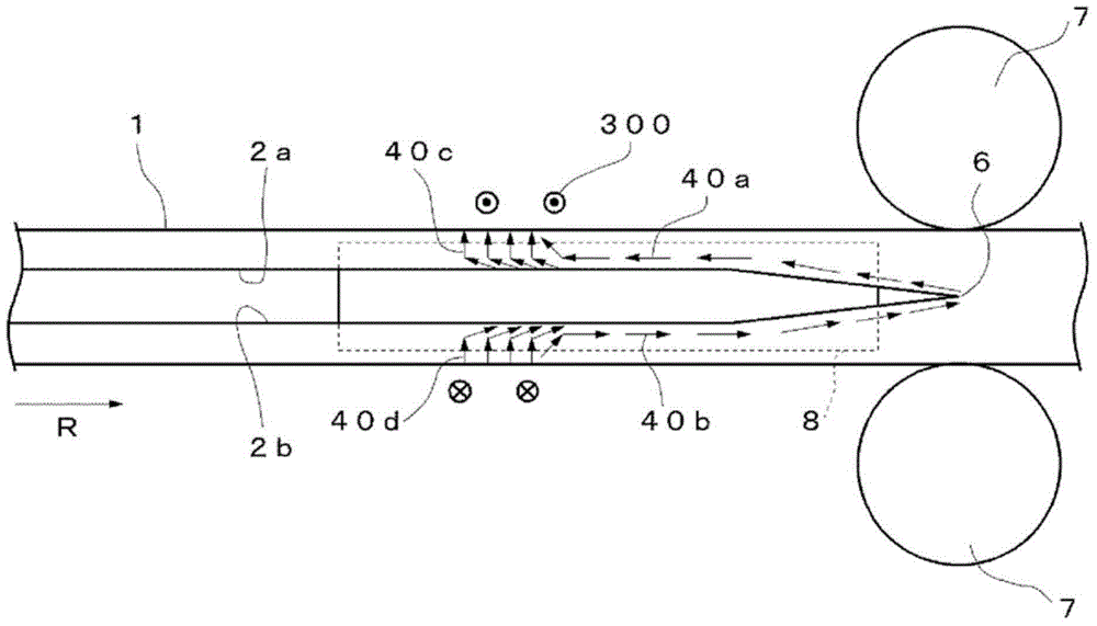
[0115] Figure 25 Is a schematic plan view showing the resistance welded pipe welding device 60 of the second embodiment of the present invention, Figure 26 Is a schematic representation in use Figure 25 The shown resistance welded pipe welding device 60 is a plan view of the distribution of the induced current generated during resistance welded pipe welding.

[0116] In the first embodiment described above, the case where the first ferromagnetic body 9 is arranged on the upstream side of the first induction coil 3 to suppress the induced current flowing to the upstream side of the first induction coil 3 has been described, but in this embodiment The structure adopted in the first induction coil 3 is provided on the upstream side of the first induction coil 3 to flow a primary current conductor, thereby similarly suppressing the upstream in...

no. 3 approach

[0132] Hereinafter, the resistance welded pipe welding device of the third embodiment of the present invention will be described.

[0133] Figure 34 Is a schematic plan view showing a resistance welded pipe welding device 70 according to the third embodiment of the present invention, Figure 35 Is to illustrate the use Figure 34 When the shown resistance welded pipe welding device 70 performs resistance welded pipe welding, the magnetic flux M generated by the first induction coil 3 passes through the ferromagnetic body (fifth ferromagnetic body) 12 in a schematic side view of the magnetic flux direction. Figure.

[0134] In this embodiment, in order to further improve the induction heating efficiency compared with the above-mentioned first and second embodiments, a configuration as exemplified below is adopted. In this embodiment, the same reference numerals are assigned to the same configurations in the first and second embodiments, and detailed descriptions thereof are omitted...

Embodiment 1

[0152] "The heated material"

[0153] In this embodiment, as the heated material, the following materials are used: the upper part of carbon steel pipe (SGP pipe) for piping with outer diameter: 318.5mm, wall thickness: 6.9mm, and length: 1m, such as Figure 44 As shown, a material that simulates the shape of the opening is processed by laser (hereinafter referred to as an open tube). The laser processing at this time is from Figure 44 The left end in the middle is opened according to the interval of the parallel opening: 50mm, length: 200mm, and then the angle between the vertex and both ends of the joint is 5.7 degrees, and the length is 500mm (total openings Is 700mm). In addition, the vertex is 0.5R.

[0154] "Electric resistance welded pipe welding device"

[0155] In the resistance welded pipe welding device used in this embodiment, as the induction coil, the following coil is used: The water-cooled copper pipe is 200mm in the upstream and downstream direction and 200mm in ...


PUM

PropertyMeasurementUnit
thicknessaaaaaaaaaa
lengthaaaaaaaaaa
thicknessaaaaaaaaaa

Abstract

Provided is a device for manufacturing electric resistance welded pipe that joins both of the end sections (2a, 2b) of an open pipe (1) at a joining section, said end sections (2a, 2b) facing an opening (2) in the open pipe (1) that extends in the direction in which said pipe runs. Joining is achieved by causing the end sections (2a, 2b) to melt using induction current generated by an induction heating means. The induction heating means comprises a first induction coil (3). The first induction coil (3) is arranged above the opening (2) without surrounding the outer periphery of the open tube (1) so that a primary current circuit that spans the opening (2) is formed.

Description

Technical field [0001] The present invention relates to an electric resistance welded pipe manufacturing device, which is used for induction heating by bending a metal strip plate into a cylindrical shape while moving it, and welding the two ends of the metal strip plate by a current induced in the metal strip plate. Background technique [0002] Generally, as methods for manufacturing metal pipes, in addition to resistance welded pipes, spiral pipes, etc., which are formed into a tube shape by welding while bending a metal strip, there are also seamless pipes manufactured by directly perforating a metal blank, and based on extrusion The method of manufacturing the tube. [0003] Resistance welded pipes are produced in large quantities because they have particularly high productivity and can be manufactured at low prices. This kind of electric resistance welded pipe is formed into a cylindrical shape while moving the metal strip to form an open pipe, and then, at the end of the sp...

Claims


Application Information

Patent Timeline
Patent Type & Authority Applications(China)
IPC IPC(8): B23K13/02B21C37/08B23K13/08B23K13/00
CPCB23K13/025Y02P10/25B23K13/02B23K13/08B23K2101/06
Inventor 广田芳明
Owner NIPPON STEEL CORP
Why Eureka
Try Eureka