a plant wall
A plant wall and plant trough technology, applied in the field of plant walls, can solve the problems of odor generation, breeding of bacteria, waste of water and equipment, etc., to achieve the effects of no odor, fresh air, and reduced manpower
- Summary
- Abstract
- Description
- Claims
- Application Information
AI Technical Summary
Problems solved by technology
Method used
Image

Examples
Embodiment 1
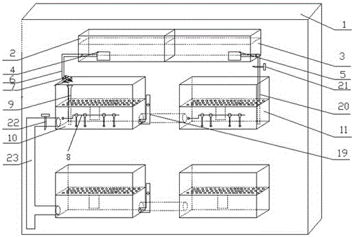
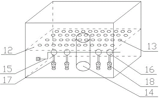
[0022] The plant wall described in this embodiment includes a partition board 1, a nutrient solution tank 2, a clear water tank 3, a filter I4, a filter II5 nutrient solution water supply pipe 6, a regulator 7, a water flow control device 8, a nutrient solution conduit 9, and a plant Groove I10, plant groove II11, clean water supply pipe 20, water stop valve I21, water delivery pipe 23; Nutrient solution tank 2 and clear water tank 3 are separated by partitions and placed on the upper ends of plant tank I10 and plant tank II11, and water pressure is used to feed water. Plants supply nutrient solution and water; nutrient solution tank 2 is provided with filter I4, and clear water tank 3 is provided with filter II5; filter I4, nutrient solution water supply pipe 6, regulator 7, and nutrient solution conduit 9 are connected in sequence, and the nutrition The liquid water supply pipe 6 and the regulator 7 are fixed on the side wall of the plant tank I10; the clear water tank 3 is p...
Embodiment 2
[0032]The plant wall described in this embodiment includes a partition board 1, a nutrient solution tank 2, a clear water tank 3, a filter I4, a filter II5 nutrient solution water supply pipe 6, a regulator 7, a water flow control device 8, a nutrient solution conduit 9, and a plant Groove I10, plant groove II11, clean water supply pipe 20, water stop valve I21, water delivery pipe 23; Nutrient solution tank 2 and clear water tank 3 are separated by partitions and placed on the upper ends of plant tank I10 and plant tank II11, and water pressure is used to feed water. Plants supply nutrient solution and water; nutrient solution tank 2 is provided with filter I4, and clear water tank 3 is provided with filter II5; filter I4, nutrient solution water supply pipe 6, regulator 7, and nutrient solution conduit 9 are connected in sequence, and the nutrition The liquid water supply pipe 6 and the regulator 7 are fixed on the side wall of the plant tank I10; the clear water tank 3 is pr...
Embodiment 3
[0035] The plant wall described in this embodiment includes a partition board 1, a nutrient solution tank 2, a clear water tank 3, a filter I4, a filter II5 nutrient solution water supply pipe 6, a regulator 7, a water flow control device 8, a nutrient solution conduit 9, and a plant Groove I10, plant groove II11, clean water supply pipe 20, water stop valve I21, water delivery pipe 23; Nutrient solution tank 2 and clear water tank 3 are separated by partitions and placed on the upper ends of plant tank I10 and plant tank II11, and water pressure is used to feed water. Plants supply nutrient solution and water; nutrient solution tank 2 is provided with filter I4, and clear water tank 3 is provided with filter II5; filter I4, nutrient solution water supply pipe 6, regulator 7, and nutrient solution conduit 9 are connected in sequence, and the nutrition The liquid water supply pipe 6 and the regulator 7 are fixed on the side wall of the plant tank I10; the clear water tank 3 is p...
PUM
 Abstract
Description
Claims
Application Information
 - R&D
- Intellectual Property
- Life Sciences
- Materials
- Tech Scout
- Unparalleled Data Quality
- Higher Quality Content
- 60% Fewer Hallucinations
Browse by: Latest US Patents, China's latest patents, Technical Efficacy Thesaurus, Application Domain, Technology Topic, Popular Technical Reports.
© 2025 PatSnap. All rights reserved.Legal|Privacy policy|Modern Slavery Act Transparency Statement|Sitemap|About US| Contact US: help@patsnap.com