Oil-fog separation blade, oil-fog separation device and application method of oil-fog separation device

An oil mist separation and blade separation technology, applied in the fields of oil mist separation blades, separation devices, and oil mist separation devices, can solve the problems of increased maintenance costs, difficult to clean grease-like dirt, and poor air suction, and achieves oil mist separation. The effect of high separation efficiency, flexible use and low production cost

Active Publication Date: 2015-04-29
陈美青
View PDF4 Cites 3 Cited by
  • Summary
  • Abstract
  • Description
  • Claims
  • Application Information

AI Technical Summary

Problems solved by technology

[0006] The oil mist collection device used in industrial production is a filter screen containing layers of overlapping filling fibers. In addition to consuming the original air flow and pressure of the filter screen, it is difficult to effectively separate the oil intercepted in the filter screen. The effect is not ideal, and the collection efficiency is low; long-term use will also block the mesh due to the aggregation of oil droplets and dust particles, resulting in poor air suction, and the air intake will gradually decrease, so that it is completely blocked; Dirt is not easy to clean and requires regular replacement, increasing maintenance costs

Method used


Image

  • Oil-fog separation blade, oil-fog separation device and application method of oil-fog separation device
  • Oil-fog separation blade, oil-fog separation device and application method of oil-fog separation device
  • Oil-fog separation blade, oil-fog separation device and application method of oil-fog separation device

Examples


Embodiment 1

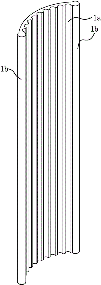
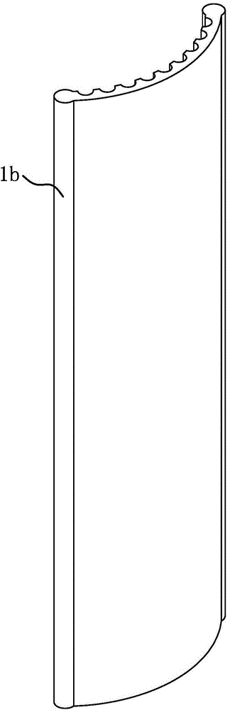
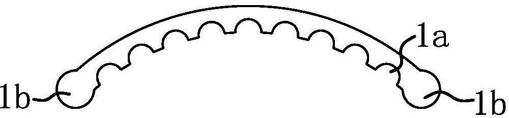
[0035] Such as Figure 1 to Figure 3 As shown, the oil mist separation blade 1 is in the shape of a strip and has an arc-shaped cross section. The concave surface of the oil mist separation blade 1 is provided with several longitudinally extending grooves 1a, and the occupied area of ​​the grooves 1a accounts for 70%-90% of the concave surface of the oil mist separation blade 1 . The number of grooves 1a given in the accompanying drawings is 9, and the cross-sectional shape of the grooves 1a is fan-shaped; according to the actual situation, the number of grooves 1a can be increased or decreased, and the cross-sectional shape of the grooves 1a can also be triangular , trapezoidal or rectangular.

[0036] The corrugated parts 1b on both sides of the oil mist separation blade 1 are cylindrical, and the corrugated parts 1b are higher than the concave surface of the oil mist separation blade 1 .

[0037] The oil mist separation blade 1 can be manufactured by continuous casting of...

Embodiment 2

[0046] The structure and principle of this embodiment are basically the same as that of Embodiment 1, and the basic similarities will not be described repeatedly, only the differences are described. The difference lies in: the column 2a of the frame 2 is provided with an oil mist separation blade 1 Corresponding hinged hole 2f and arc-shaped fixing hole 2g, one side corrugated part 1b of the oil mist separation blade 1 is embedded in the hinge hole 2f, and the arc-shaped fixing hole 2g is pierced with a screw 3, and the screw 3 and the oil mist separation blade 1 is connected to the other side corrugated portion 1b. The oil mist separation blade 1 is fixed by screwing the screw 3 .


PUM


Abstract

The invention provides an oil-fog separation blade, an oil-fog separation device and an application method of the oil-fog separation device, belongs to the technical field of working, and aims at solving the problem that oil dirt adhered to an existing filter screen is not easy to clean. The oil-fog separation blade is in a strip sheet shape and the cross section of the oil-fog separation blade is in a circular arc shape; and a concave surface of the oil-fog separation blade is provided with a plurality of grooves which extend along the vertical direction. The oil-fog separation device comprises a framework and the plurality of oil-fog separation blades fixedly arranged on the framework; the plurality of oil-fog separation blades are at least distributed on two planes parallel to a plate surface; the oil-fog separation blades are arranged in parallel; the concave surfaces in the oil-fog separation blades are arranged towards the same plate surface; and the oil-fog separation blades on the two adjacent planes parallel to the plate surface are arranged in a staggered manner. The oil-fog separation device with the oil-fog separation blades has the advantages of convenience for assembling, flexible utilization manner, high oil-fog separation efficiency and the like.

Description

technical field [0001] The invention belongs to the technical field of operations, and relates to a separation device, in particular to an oil mist separation blade. [0002] The invention belongs to the field of operation technology, and relates to a separation device, in particular to an oil mist separation device. [0003] The invention belongs to the field of operation technology, and relates to a separation device, in particular to a use strategy of an oil mist separation device. Background technique [0004] A large amount of oil mist is produced in the daily cooking process and industrial production process. If it is directly discharged into the atmosphere, it will seriously pollute the environment, especially PM2.5. [0005] Various designs have been proposed to separate the oil from the gas stream. For example, when the direct gap between the vertical bar 111 of the front filter plate and the vertical bar 125 of the rear filter plate in a kind of range hood air in...

Claims


Application Information

Patent Timeline
IPC IPC(8): B01D45/08
CPCB01D45/08
Inventor 陈美青
Owner 陈美青
Why Eureka
Try Eureka