Method for preparing microsphere FCC (fluid catalytic cracking) catalyst

A catalyst and catalyst slurry technology, applied in molecular sieve catalysts, chemical instruments and methods, physical/chemical process catalysts, etc., can solve the problems of easy catalyst wear, increased agent consumption, poor catalyst sphericity, etc., and achieves good atomization effect. Improve the atomization effect and the effect of good sphericity

Active Publication Date: 2015-04-29
CHINA PETROLEUM & CHEM CORP +1
View PDF3 Cites 4 Cited by
  • Summary
  • Abstract
  • Description
  • Claims
  • Application Information

AI Technical Summary

Problems solved by technology

Catalysts with poor sphericity are prone to wear during use
The running loss of fine powder produced by wear will not only increase the consumption of catalyst but also pollute the environment; in addition, the fine powder produced by catalyst wear may also affect subsequent equipment such as hoods, which is unfavorable for the long-term operation of the catalytic cracking unit
[0003] CN1160436C discloses a method for preparing a catalytic cracking catalyst, which uses the viscosity of the catalyst slurry as a control index to adjust the amount of inorganic acid added during the acidification of pseudo-boehmite, and this method can avoid fluctuations in acid consump

Method used


Image

  • Method for preparing microsphere FCC (fluid catalytic cracking) catalyst
  • Method for preparing microsphere FCC (fluid catalytic cracking) catalyst
  • Method for preparing microsphere FCC (fluid catalytic cracking) catalyst

Examples


Example Embodiment

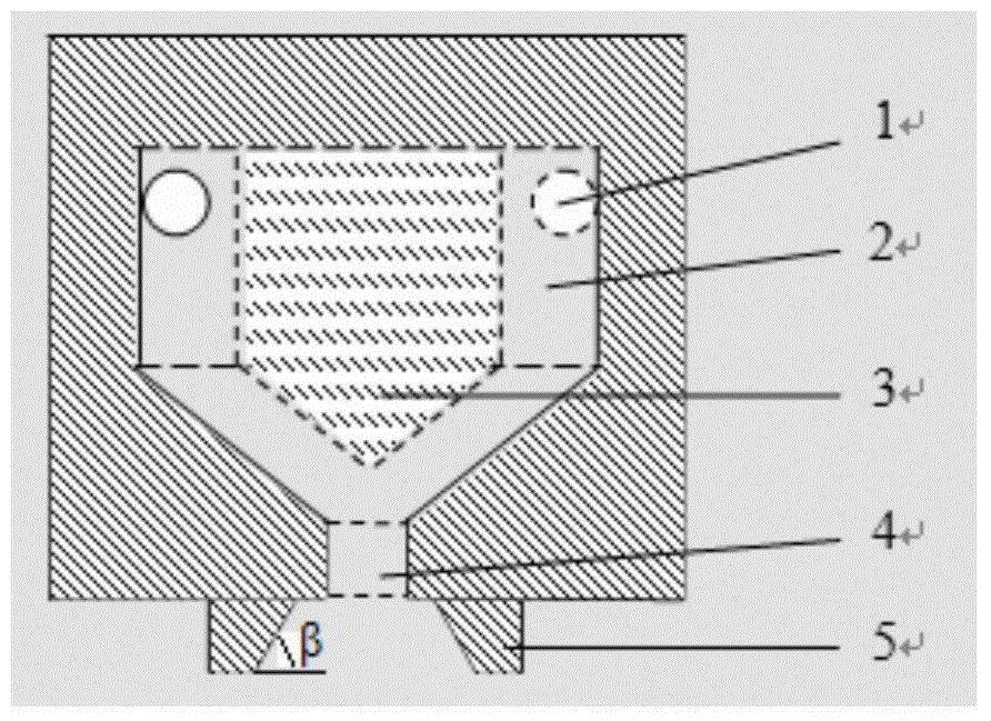
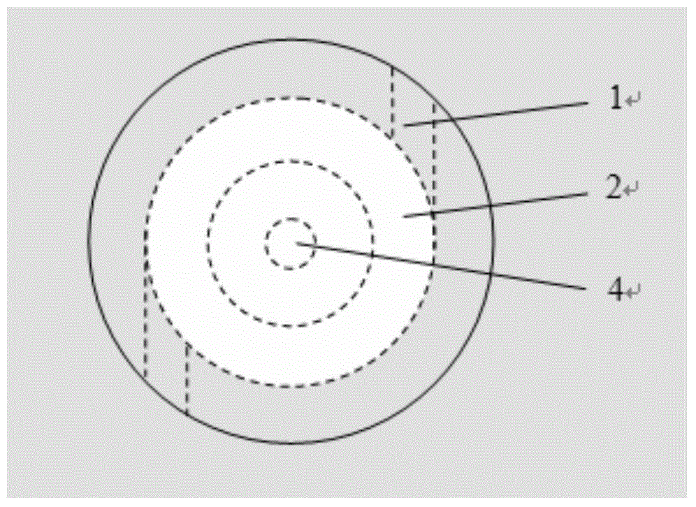
[0040] According to a preferred embodiment of the present invention, the diameter of the nozzle inlet is 1-8mm, the ratio of the length to the diameter of the nozzle inlet is 0.5-5.0; the cavity diameter of the nozzle body is 10-40mm; the diameter of the nozzle hole The nozzle inlet diameter is greater than or equal to the diameter of the nozzle hole is 2-10mm, and the height of the nozzle hole is 1-8mm; the flow guide includes a connected cylinder and a cone, and the nozzle body includes a connected cylinder and a cone The cavity includes a cylindrical cavity and a conical cavity connected, and the cone angle of the cone of the nozzle body and the cone angle of the cone of the flow guide are equal to the cone angle of the conical cavity.

[0041] The height of the cylindrical section of the nozzle body is 1.5-15mm, and the height of the cone section of the nozzle body is 3-15mm; the diameter of the cylindrical section of the flow guide is larger than the diameter of the nozzle ho...

Example Embodiment

[0063] Example 1

[0064] Such as figure 1 As shown, the 1# nozzle includes: a protective cover with a horn opening and a cavity adapted to the size of the nozzle body (such as figure 1 As shown), the horn opening is connected to the nozzle hole (the central axis of the horn opening coincides with the central axis of the nozzle hole, and the height of the horn opening is 1 / 5 of the cavity height), and the angle between the bus bar of the horn opening and the horizontal line is 45 °, the maximum diameter of the horn opening is 5 times the diameter of the nozzle hole, and the minimum diameter is 2 times the diameter of the nozzle hole; a nozzle body with a cavity, the nozzle body including a connected cylinder and a cone, the cavity Including a connected cylindrical cavity and a conical cavity, the nozzle body is provided with 2 uniformly distributed nozzle inlets (the diameter of the nozzle inlet is 1.8mm, the length of the nozzle inlet is 3.0mm) and one nozzle hole (the diameter o...

Example Embodiment

[0068] Example 2

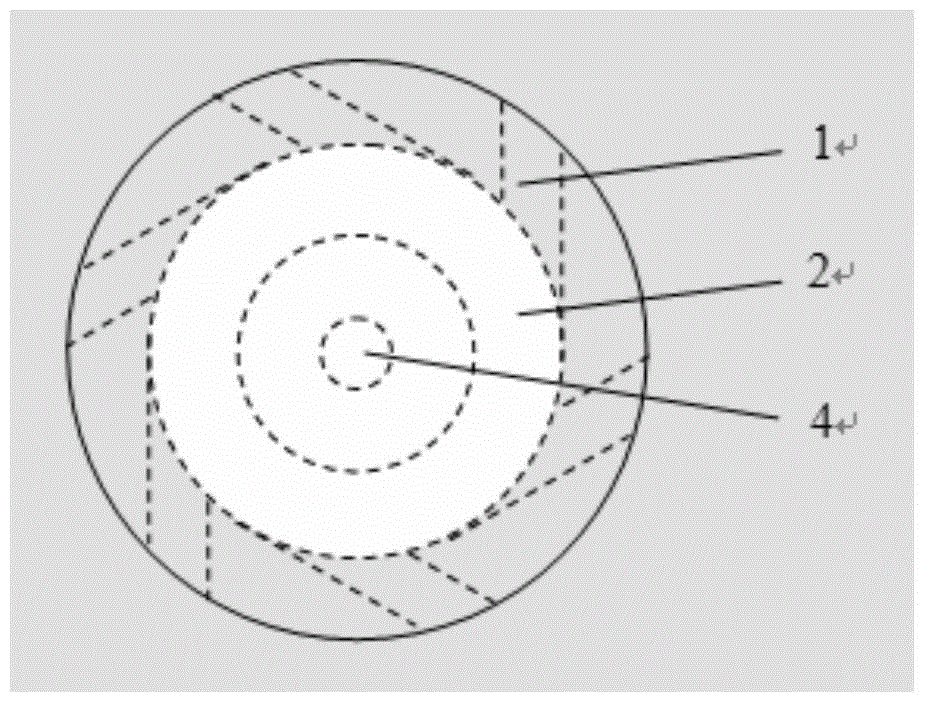
[0069] Such as figure 1 As shown, the 2# nozzle includes: a protective cover with a horn opening and a cavity adapted to the size of the nozzle body (such as figure 1 As shown), the horn opening is connected with the nozzle hole (the central axis of the horn opening coincides with the central axis of the nozzle hole, and the height of the horn opening is 1 / 2 of the cavity height), and the angle between the bus bar of the horn opening and the horizontal line is 60 °, the maximum diameter of the horn opening is 8 times the diameter of the nozzle hole, and the minimum diameter is 1 time the diameter of the nozzle hole; a nozzle body with a cavity, the nozzle body includes a connected cylinder and a cone, the cavity Including a connected cylindrical cavity and a conical cavity, the nozzle body is provided with 6 evenly distributed nozzle inlets (the diameter of the nozzle inlet is 2.8mm, the length of the nozzle inlet is 3.5mm) and one nozzle (the diameter of the no...


PUM

PropertyMeasurementUnit
Viscosityaaaaaaaaaa

Abstract

The invention provides a method for preparing a microsphere FCC (fluid catalytic cracking) catalyst, wherein the method comprises the following steps: beating a molecular sieve, clay, pseudo boehmite and acid to obtain catalyst slurry, and spray-drying the catalyst slurry, and in the spray-drying process, spraying is performed through a spray nozzle, then drying is performed, and the spray nozzle comprises a spray nozzle main body with a cavity, wherein a spray nozzle inlet and spray holes are formed in the spray nozzle main body, a diversion part protrudes downwards from the top wall of the cavity of the spray nozzle main body, and the space between the outer surface of the diversion part and the inner surface of the cavity forms a rotation chamber. When the spray nozzle provided by the invention is used for spray-drying, the atomization effect is good, and when the spray nozzle is used for spray-drying to prepare the FCC catalyst, the prepared FCC catalyst has good sphericility. By adopting the method provided by the invention, the microsphere FCC catalyst with good sphericility can be obtained.

Description

technical field [0001] The invention relates to a method for preparing microsphere FCC catalyst. Background technique [0002] The shape of FCC catalyst particles is very close to that of a sphere observed under a microscope, but not all FCC catalyst particles are complete spheres, and there are large differences in their shapes. The sphericity of FCC catalyst refers to the degree of shape similarity between FCC catalyst particles and spheres. Sphericity is an important physical property of FCC catalysts. The sphericity of FCC catalyst not only affects the fluidization performance of the catalyst, but also is closely related to the wear resistance of the catalyst. Catalysts with poor sphericity are prone to wear during use. The running loss of fine powder produced by wear will not only increase the consumption of catalyst but also pollute the environment; in addition, the fine powder produced by catalyst wear may also affect subsequent equipment such as hoods, which is no...

Claims


Application Information

Patent Timeline
IPC IPC(8): B01J35/08B01J29/08
Inventor 严加松张志民张剑秋陶金赵留周孙好现田辉平张蓬蓬朱玉霞贾慧宁博
Owner CHINA PETROLEUM & CHEM CORP
Why Eureka
Try Eureka