A spray coater of an electric control system

An electrical control system, spraying machine technology, applied in coating, spray booth, spraying device and other directions, can solve the problems of poor surface quality, low work efficiency, poor adhesion performance, etc., to improve work efficiency, good production operation requirements, The effect of reducing product cost

Inactive Publication Date: 2015-04-29
HEILONGJIANG KANGGEER TECH
View PDF0 Cites 0 Cited by
  • Summary
  • Abstract
  • Description
  • Claims
  • Application Information

AI Technical Summary

Problems solved by technology

[0002] At present, among the surface coating process equipment used in my country for automobiles, tractors, agricultural machinery, etc., the traditional coating process equipment is to use paint spraying cabinets, spray water on the facade to form a water curtain to absorb paint mist, and use resistance wires for drying furnaces. Heating, but with the rapid growth of national agriculture, industry, forestry and other machinery, there are many defects in traditional craft equipment, such as low work efficiency, poor surface quality and poor adhesion performance, which are far from meeting the actual needs of many users. For this reason, We have designed a new type of coating equipment that uses underground water curtains to absorb paint mist and heats and dries liquefied petroleum gas. This coating equipment has novel structure, excellent performance, high work efficiency, convenient operation, and meets environmental hygiene requirements. It can meet the requirements of various steel plates. It can not only improve the surface quality of parts, but also save manpower and material resources for enterprises, save money, reduce product costs, and improve market competitiveness, which has great promotion value.

Method used


Image

  • A spray coater of an electric control system
  • A spray coater of an electric control system

Examples


Embodiment Construction

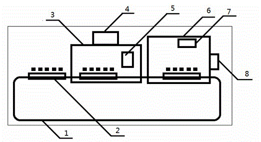
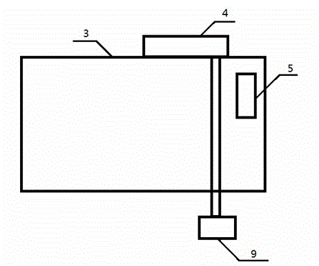
[0012] Such as figure 1 , figure 2 , as shown, a spraying machine with an electrical control system, including a conveyor belt 1, a number of loading plates 2, a paint spraying room 3, a brushing device 5, a sewage discharge system 4 in the painting room, an air supply system 7, an electrical control system 8, and a drying Room 6, the carrier board 2 is fixed on the conveyor belt 1 by screw device, the conveyor belt 1 is installed on the guide rail on the front ground of the spray booth 3, the sewage system 4 of the spray booth is installed outside the middle part of the spray booth 3, and the brushing device 5 is installed on the The end of the paint spraying room 3, the drying room 6 is connected with the painting room 3, the air supply system 7 is in the drying room 6, and the electrical control system 8 is installed on the outside of the drying room 6.

[0013] Described brushing device 5 is a roller brush.

[0014] The conveyor belt 1 is an endless belt, and the belt b...


PUM


Abstract

The invention relates to a spray coater of an electric control system. The spray coater comprises a conveyor belt, a plurality of object carrying plates, a paint spraying chamber, a brushing supplement device, a sewerage system of the paint spraying chamber, an air supplying system, the electric control system and a drying chamber. The object carrying plates are fixed on the conveyor belt through screw devices. The conveyor belt is installed on a guide rail on the ground in the front of the paint spraying chamber. The sewerage system of the paint spraying chamber is installed at the outside of the middle of the paint spraying chamber. The brushing supplement device is installed at the tail end of the pain spraying chamber. The drying chamber is connected to the paint spraying chamber. The air supplying system is disposed in the drying chamber. The electric control system is installed at the outside of the drying chamber. The spray coater is simple in structure, economical and practical, provides a coating device with a simple structure, improves paint coating quality of components and largely increases the working efficiency.

Description

technical field [0001] The invention relates to a spraying machine with an electric control system, which belongs to the field of machinery. Background technique [0002] At present, among the surface coating process equipment used in my country for automobiles, tractors, agricultural machinery, etc., the traditional coating process equipment is to use paint spraying cabinets, spray water on the facade to form a water curtain to absorb paint mist, and use resistance wires for drying furnaces. Heating, but with the rapid growth of national agriculture, industry, forestry and other machinery, there are many defects in traditional craft equipment, such as low work efficiency, poor surface quality and poor adhesion performance, which are far from meeting the actual needs of many users. For this reason, We have designed a new type of coating equipment that uses underground water curtains to absorb paint mist and heats and dries liquefied petroleum gas. This coating equipmen...

Claims


Application Information

Patent Timeline
Patent Type & Authority Applications(China)
IPC IPC(8): B05C9/14
CPCB05B16/95B05B16/20
Inventor 不公告发明人
Owner HEILONGJIANG KANGGEER TECH
Why Eureka
Try Eureka