Universal finger joint force feedback unit

A technology of feedback unit and metacarpophalangeal joints, applied in manipulators, manufacturing tools, etc., can solve problems such as difficult maintenance, expensive force feedback data gloves, and complex systems

Inactive Publication Date: 2015-04-29
苏茂
View PDF4 Cites 3 Cited by
  • Summary
  • Abstract
  • Description
  • Claims
  • Application Information

AI Technical Summary

Problems solved by technology

[0003] The purpose of the present invention is to solve the disadvantages of the existing force feedback data gloves, such as high price, complex system, and difficult maintenance, and proposes a combination of an external angle sensor and a joint two-way active drive device, which is used to detect the movement information of human hand joints. At the same time, it also converts the feedback force sensory information into a force or torque that directly acts on the human hand, which greatly simplifies the complex force feedback data glove system

Method used


Image

  • Universal finger joint force feedback unit
  • Universal finger joint force feedback unit
  • Universal finger joint force feedback unit

Examples


specific Embodiment approach 1

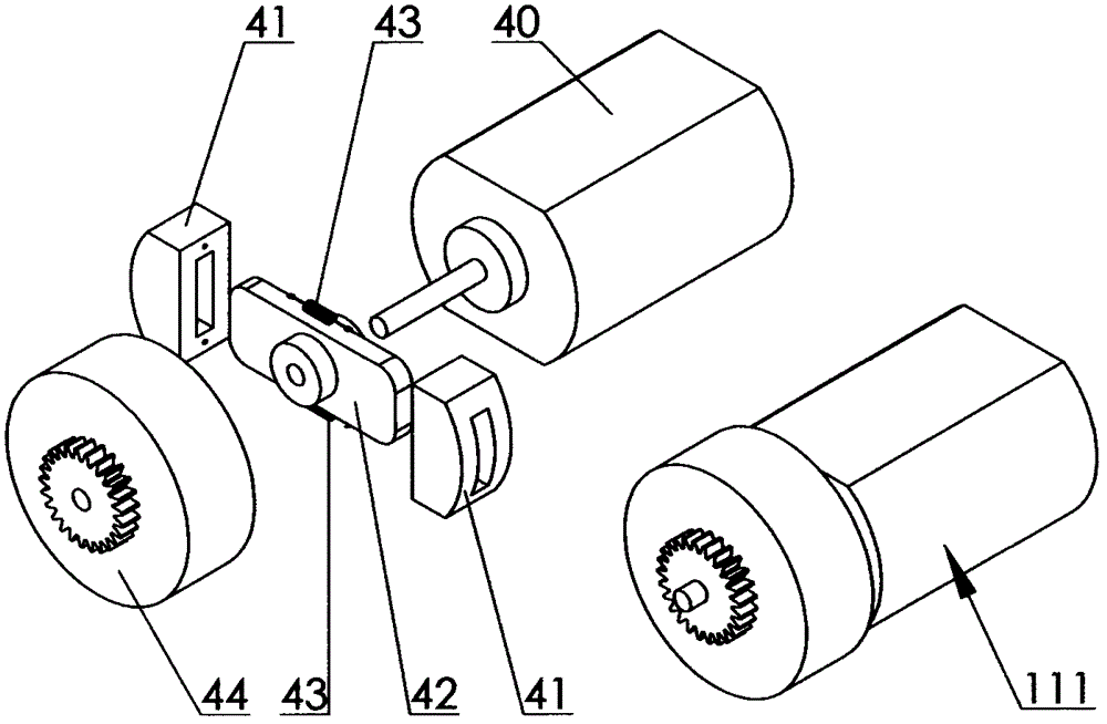
[0007] Specific implementation manner one: such as image 3 As shown, the driving component 111 includes a micro motor 40 and a clutch. The clutch is composed of a clutch friction plate 41, a friction plate sliding rod 42, a return tension spring 43, and a clutch cover 44. The friction plate sliding rod 42 and the micro The shaft of the motor 40 is fixedly connected, the two clutch friction plates 41 are respectively sleeved into the two ends of the friction plate sliding rod 42, the return tension spring 43 is connected between the two clutch friction plates 41, and the clutch cover 44 is sleeved on the shaft of the micro motor 40 , The clutch cover 44 is in sliding contact with the shaft of the micro motor 40, and the clutch cover 44 is provided with a transmission gear. Action implementation process: When the speed of the micro motor 40 is higher than a certain value, the two clutch friction plates 41 overcome the pulling force of the return tension spring 43 to slide to the...

specific Embodiment approach 2

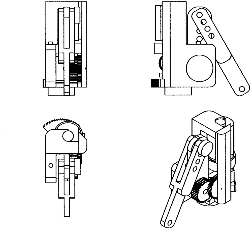
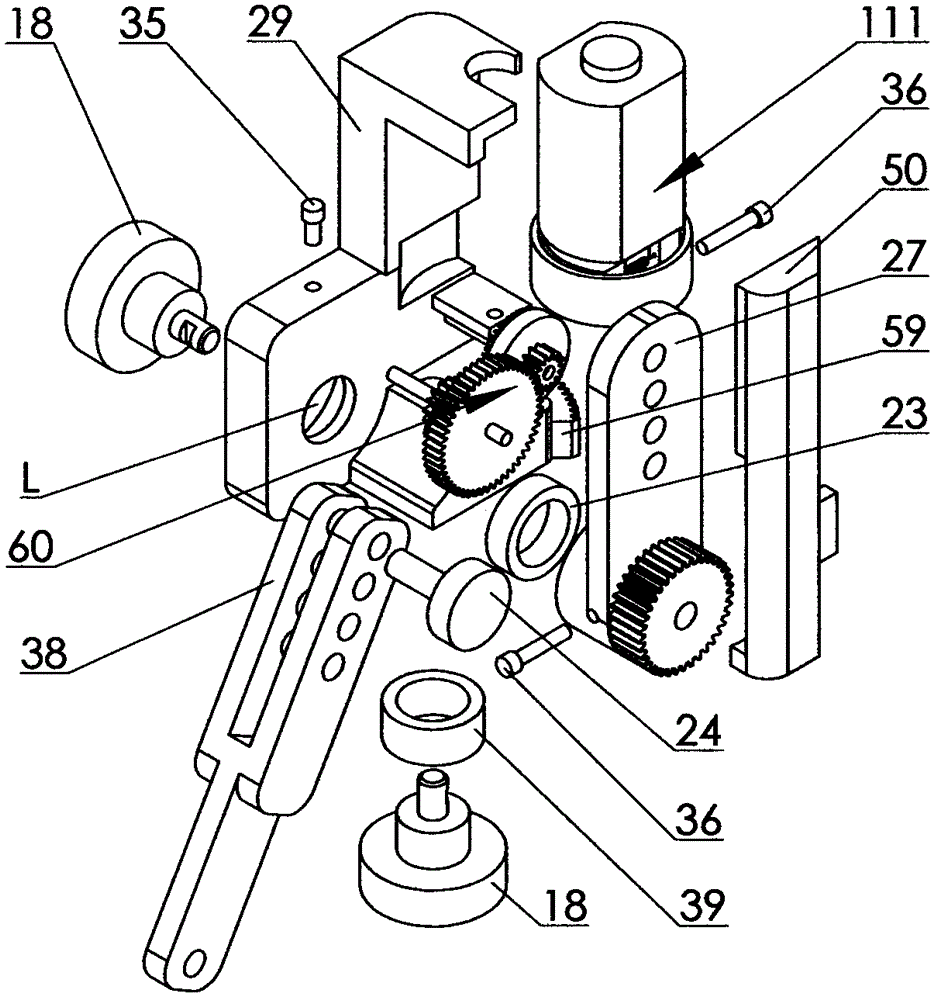
[0008] Specific implementation manner two: such as figure 1 , figure 2 with image 3 As shown, the universal palm-phalangeal joint force feedback unit includes a driving component 111, a rocker arm 27, a metacarpophalangeal joint base 29, a connecting rod 38, a gear box cover 50 and two angle sensors 18. The bottom of the metacarpophalangeal joint base 29 (embedded bearing 39) is fixed to the axis of an angle sensor 18 by screws 36. The metacarpophalangeal joint base 29 can rotate around the axis of the bottom angle sensor 18. The lower outer edge of the base 29 is provided with a gear 59. The axis of the gear 59 coincides with the axis of the angle sensor 18 at the bottom of the metacarpophalangeal joint base 29. The other angle sensor 18 is fixed on the metacarpophalangeal joint base 29 by a screw 35. In the hole seat L, the shaft of the angle sensor 18 and one end of the rocker arm 27 (the embedded bearing 23) are fixedly connected by a screw 36. The gear axis on the rocker...


PUM


Abstract

The invention discloses a universal finger joint force feedback unit and relates to a device capable of detecting human finger motion states and feeding force applied on the corresponding finger joints of a manipulator back. In order to solve the problems that a joint measuring mechanism and a force feedback mechanism of an existing force feedback device are separated and the system is complicated and bloated in the structure and difficulty to maintain and overcome the defect that bidirectional active driving cannot be realized and price is high, the joint detecting mechanism and the force feedback mechanism are integrated, and joint measuring points are arranged in the unique and ingenious connection mode. Accordingly, when operating the equipment, operators can keep most flexibly use the detected fingers, motion states can be accurately detected, and the finger joints of the manipulator can be controlled to be coordinative to the corresponding finger joints of the operators, and stress conditions of the manipulator in the specific operating environment can be fed back to the operators so as to enhance field feeling of virtual reality or remote operation.

Description

Technical field [0001] The invention relates to a device for detecting the movement state of the fingers of a human hand and having the function of bidirectional feedback force. Background technique [0002] Due to the development of science and technology, robots are gradually being used in a larger and larger range. As a reliable and mature robot, teleoperation robots are widely used in various dangerous, complicated and inaccessible environments. It uses a very reliable control method, which is controlled by the operator directly. As the tasks performed by teleoperated robots become more and more complex, people are pursuing reliability while also putting forward higher requirements for their flexibility. However, it is necessary to remotely operate complex manipulators and control the multiple fingers of the manipulator. Multiple joints coordinate movement together to achieve specific functions, which requires the use of data gloves, and the data gloves with force feedback f...

Claims


Application Information

Patent Timeline
IPC IPC(8): B25J13/08
Inventor 苏茂
Owner 苏茂
Why Eureka
Try Eureka