Film tearing mechanism

A technology of protective film and manipulator, applied in lamination auxiliary operation, lamination, layered products, etc., can solve the problem of easily damaged product surface, etc., and achieve the effect of high work efficiency

Active Publication Date: 2015-04-29
FU DING ELECTRONICSAL TECH JIASHAN +2
View PDF4 Cites 16 Cited by
  • Summary
  • Abstract
  • Description
  • Claims
  • Application Information

AI Technical Summary

Problems solved by technology

However, the above film tearing mechanism uses a spatula to scrape off the protective film, which is more likely to damage the product surface

Method used


Image

  • Film tearing mechanism
  • Film tearing mechanism
  • Film tearing mechanism

Examples


Embodiment Construction

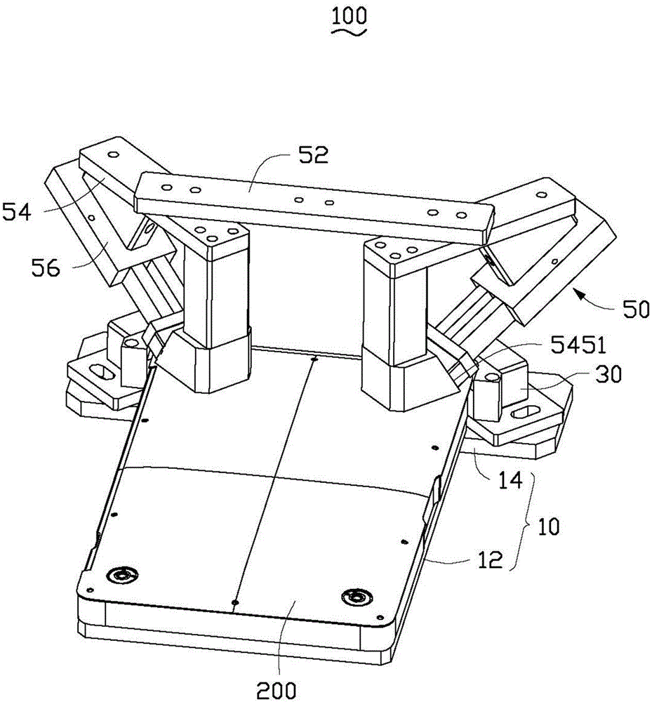
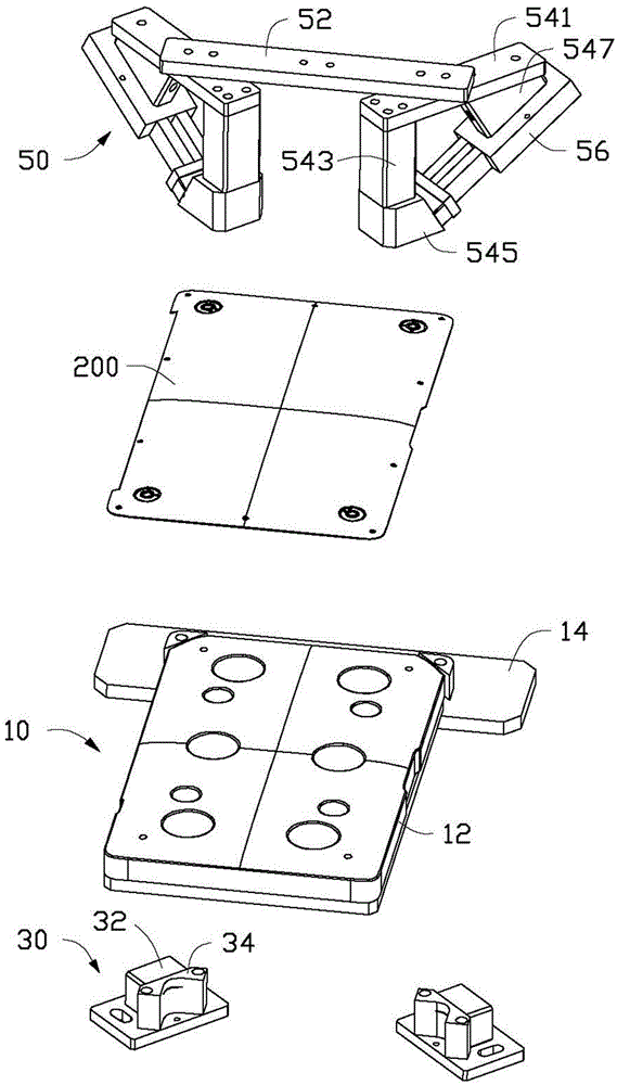
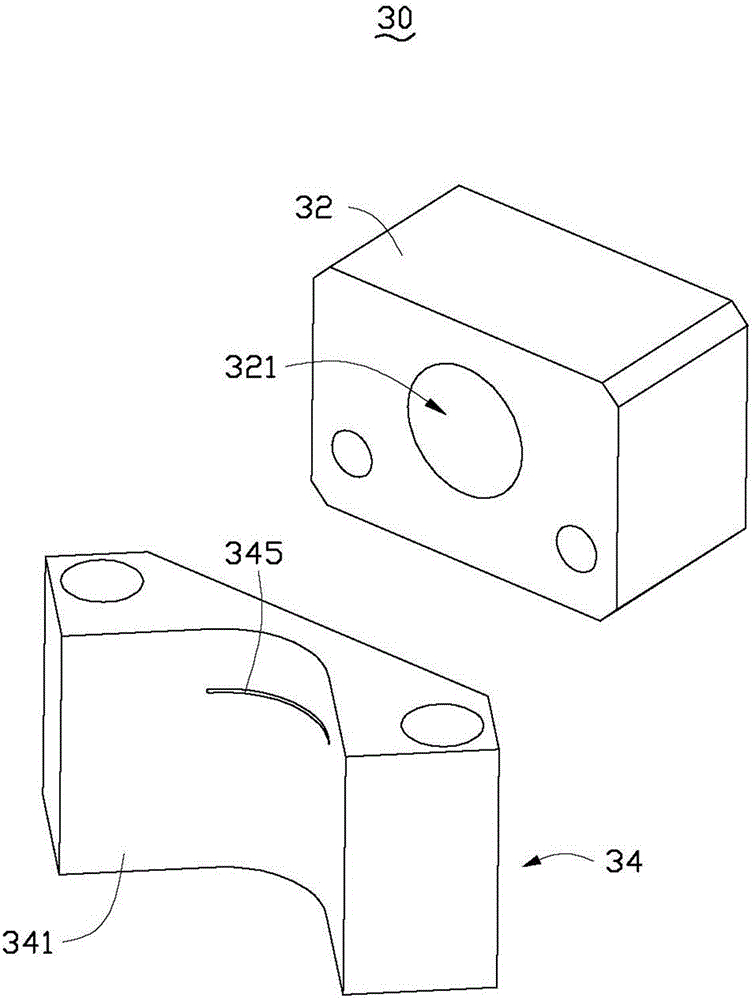
[0015] See figure 1 and figure 2 , The film tearing mechanism 100 of the embodiment of the present invention is used to assist a robot (not shown) to tear off the protective film (not shown) on the surface of the sheet-like workpiece 200. The film tearing mechanism 100 includes a fixing base 10, an air blowing assembly 30 arranged on the fixing base 10, and a clamping assembly 50 arranged adjacent to the air blowing assembly 30.

[0016] The fixing base 10 is roughly in the shape of a “T” plate, and includes a supporting portion 12 and two mounting portions 14 adjacent to the supporting portion 12. The carrying portion 12 is used to carry the workpiece 200. In this embodiment, the shape of the carrying portion 12 is adapted to the outer shape of the workpiece 200, and is roughly in the shape of a rectangular plate. The two installation parts 14 are respectively arranged adjacent to two adjacent corners of the supporting part 12, and are used for installing the air blowing assemb...


PUM

PropertyMeasurementUnit
widthaaaaaaaaaa

Abstract

A film-removing mechanism configured to cooperate with a mechanical arm to remove a protecting film from a workpiece can include a base, a blowing member coupled to the base, and a holding assembly positioned adjacent to the blowing member. The base can be configured to support the workpiece. The blowing member defining an air outlet can be configured to communicate with an external air resource. The holding assembly can include a supporting member positioned adjacent to the base and a driving member coupled to the supporting member. The supporting member can correspond to the air outlet and the driving member can be configured to connect to the external mechanical arm.

Description

Technical field [0001] The invention relates to a film tearing mechanism, in particular to a film tearing mechanism for peeling a protective film on the surface of a product. Background technique [0002] In manufacturing, before processing, many products have a protective film attached to the surface, and the protective film needs to be removed during processing. Usually, the manual tearing of the film is used. The corner of the protective film is first lifted, and then the protective film is torn away from the workpiece. Manual tearing of the film consumes a lot of manpower, low work efficiency, and manual operation is easy to stain the surface of the product, which is not conducive to subsequent processing. At present, people are beginning to use automatic tearing mechanism to tear the film. The automatic film tearing mechanism includes a blade and a clamp with a slope. The blade is movably installed for scraping and tearing off the protective film. The clamp is used to ho...

Claims


Application Information

Patent Timeline
Patent Type & Authority Applications(China)
IPC IPC(8): B32B38/10
CPCB32B43/006B32B38/10Y10T156/1137Y10T156/1939
Inventor 吕小勇邓小名
Owner FU DING ELECTRONICSAL TECH JIASHAN
Why Eureka
Try Eureka