Automobile engine suspension mounting structure

A technology of automobile engine and installation structure, which is applied in the direction of power plant, vehicle parts, transportation and packaging, etc. It can solve the problems of failure to meet NVH performance requirements, failure of rear suspension cushions, low bracket mode, etc., and achieve low noise, Ingenious design and long service life

Inactive Publication Date: 2015-04-29
CHONGQING KAITE POWER SCI & TECH
View PDF5 Cites 5 Cited by
  • Summary
  • Abstract
  • Description
  • Claims
  • Application Information

AI Technical Summary

Problems solved by technology

[0005] The main problem in the structure of the rear suspension cushion assembly is that the transmission drives the upper plate of the suspension to rush forward during sudden braking, and there is no corresponding anti-sprint limit structure on the rear suspension to prevent the upper plate of the suspension from being too large. ;When reversing and braking suddenly, the transmission drives the upper plate of the suspension to rush backwards, and the corresponding anti-backlash structure is not installed on the rear suspension to prevent the rear impact of the upper plate of the suspension from being too large
Whether the front impulse is too large or the rear impulse is too large, it may cause the engine to collide with other parts and deform when it is working, and cause the rubber damping pad to be cut off due to excessive shearing force, eventually causing the rear suspension to be damaged. The soft cushion assembly is in failure state, which constitutes a certain safety hazard
[0006] In addition, the existing automobile engine rear suspension bracket is usually a stamped "U"-shaped frame, which is a left-right symmetrical part, and the bracket mode is low, which cannot avoid the second-order and fourth-order excitation of the engine, resulting in resonance and affecting the rear suspension. device life, unable to meet NVH performance requirements

Method used


Image

  • Automobile engine suspension mounting structure
  • Automobile engine suspension mounting structure
  • Automobile engine suspension mounting structure

Examples


Embodiment 1

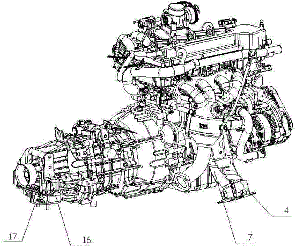
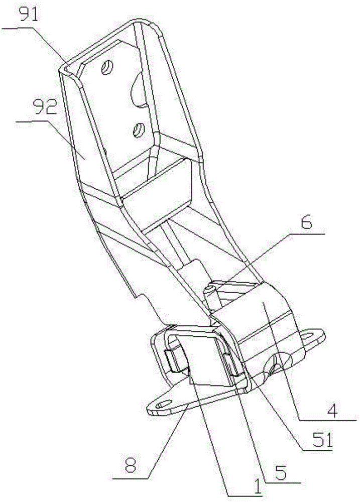
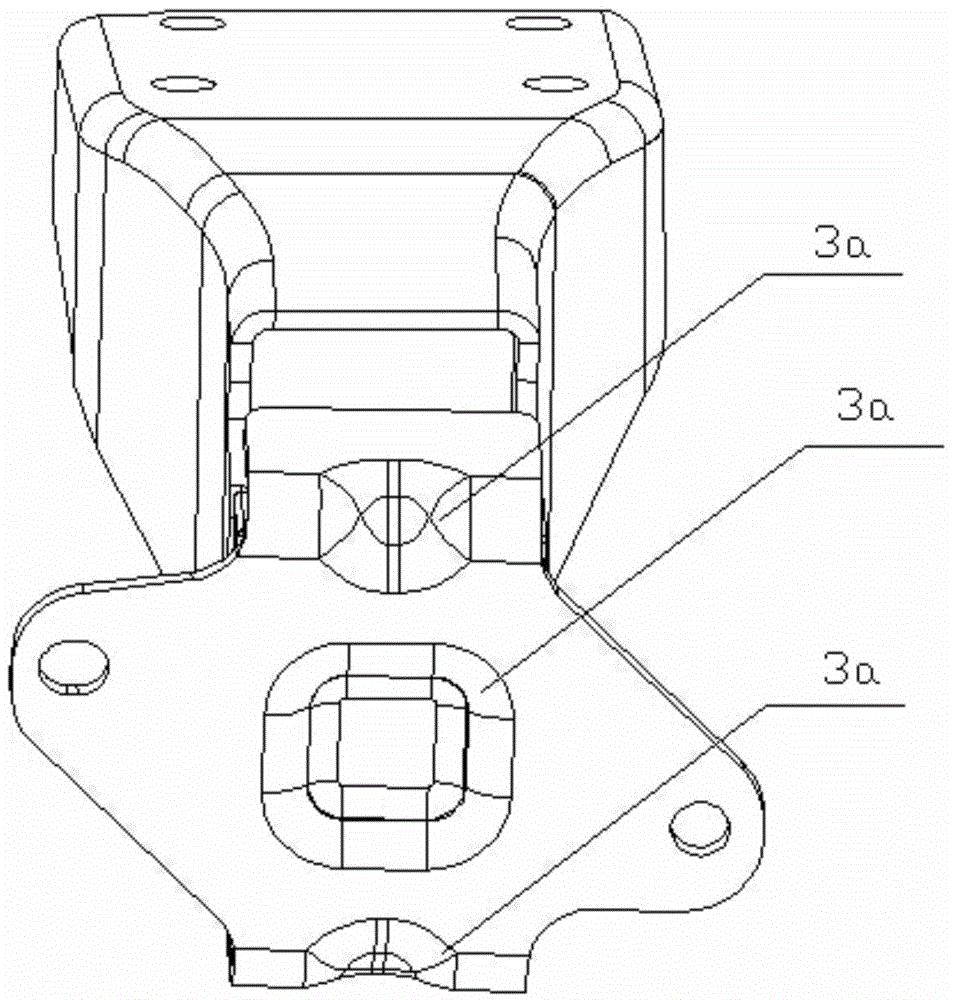
[0039] Such as Figure 1-13 Shown: an automobile engine suspension installation structure of the present invention is composed of a cylinder block, a transmission, a left suspension, a right suspension and a rear suspension. The engine includes a cylinder block, a transmission and other components. This is the prior art, here Do not repeat it. The left and right suspensions are respectively installed on the left and right sides of the cylinder, and the rear suspension is installed on the rear housing of the transmission. The left suspension and the right suspension have the same structure, including the elastic body 1, the upper limit block 2. The lower limit block 3 and the suspension bracket 9 connected with the cylinder by bolts, the rear suspension includes a rear suspension bracket 16 and a rear suspension cushion assembly 17.

[0040] The left and right suspension of the engine is composed of elastic body 1, upper limit block 2, lower limit block 3, limit part 4, rubber sh...


PUM


Abstract

The invention discloses an automobile engine suspension mounting structure. A left suspension and a right suspension are mounted on the left side and the right side of a cylinder body respectively, a rear suspension is mounted on a tail housing of a transmission, each of the left suspension and the right suspension comprises an elastomer, an upper limiter, a lower limiter and a suspension support, the rear suspension comprises a rear suspension support and a rear suspension cushion assembly, the side plates of the lower limiters extend upwards, the upper portions of the extending parts of the lower limiters are folded inwards to form limit portions, the rear suspension support is a 'U'-shaped frame, the left end and the right end of an upper suspension plate extend downwards and extend horizontally towards the inner side after overpassing the ends of a lower suspension plate, and the middle of the front end of the lower suspension plate first extends forwards and then extends vertically upwards to form a forward-rush preventing limit plate. A forward-rush preventing rubber cushion block is sleeved with the forward-rush preventing limit plate, the middle of the rear end of the lower suspension plate extends backwards and then extends vertically upwards to form a backward-rush preventing limit plate, and a backward-rush preventing rubber cushion block is sleeved with the backward-rush preventing limit plate. The automobile engine suspension mounting structure is not easy to fail.

Description

Technical field [0001] The invention relates to an automobile engine suspension installation structure. Background technique [0002] The engine is the heart of a car, and its performance directly determines the performance of the car. Since the engine itself is a vibration source, and at the same time, it is interfered by various external vibrations. Therefore, a power suspension system is usually set to Reduce the transmission of vibration generated by the engine to the supporting parts, or various external vibrations that interfere with the normal operation of the engine. [0003] At present, the power suspension system generally includes the current rear suspension left and right suspension and the rear suspension. The left and right suspensions are installed on the left and right sides of the cylinder block, and the rear suspension is installed on the rear housing of the transmission. The left and right suspensions in vehicles mainly use suspension cushions as the main compon...

Claims


Application Information

Patent Timeline
Patent Type & Authority Applications(China)
IPC IPC(8): B60K5/12F16F15/08
Inventor 白天明延虎和艳萍张志义苏宏
Owner CHONGQING KAITE POWER SCI & TECH
Why Eureka
Try Eureka