Supercharge Your Innovation With Domain-Expert AI Agents!

Self-anchored suspension bridge anchored span cast-in-situ concrete box girder and its construction method

A technology of self-anchored suspension bridges and concrete box girders, which is applied in the direction of suspension bridges, bridges, bridge parts, etc., can solve the problems of difficult construction of concrete box girders, complex stress and structural measures, and no mature and reliable methods, so as to achieve shortening The construction period, the structure is simple, and the effect of reasonable arrangement

Active Publication Date: 2017-02-01
CHINA RAILWAY CONSTR GROUP +2
View PDF9 Cites 0 Cited by
  • Summary
  • Abstract
  • Description
  • Claims
  • Application Information

AI Technical Summary

Problems solved by technology

With the development of related technologies, a combined system of steel stiffened beams and concrete stiffened beams has been applied; this combined system uses steel stiffened beams in the sling area and concrete stiffened beams in the anchor spans on both sides, although this system It has the advantages of both steel structure and concrete structure, but due to the complex force and structural measures of the steel-concrete combined beam section and the anchorage area, the construction of the anchored span concrete box girder is quite difficult; for the construction of the anchored span cast-in-place concrete box girder, There is currently no mature and reliable method
In the specific construction, it is often reworked due to poor consideration, and even leaves quality hidden dangers

Method used


Image

  • Self-anchored suspension bridge anchored span cast-in-situ concrete box girder and its construction method
  • Self-anchored suspension bridge anchored span cast-in-situ concrete box girder and its construction method
  • Self-anchored suspension bridge anchored span cast-in-situ concrete box girder and its construction method

Examples


Embodiment Construction

[0038] The following will clearly and completely describe the technical solutions in the embodiments of the present invention with reference to the accompanying drawings in the embodiments of the present invention. Obviously, the described embodiments are only some, not all, embodiments of the present invention. All other embodiments obtained by persons of ordinary skill in the art based on the embodiments of the present invention belong to the protection scope of the present invention.

[0039] According to an embodiment of the present invention, a self-anchored suspension bridge is provided with an anchored-span cast-in-situ concrete box girder.

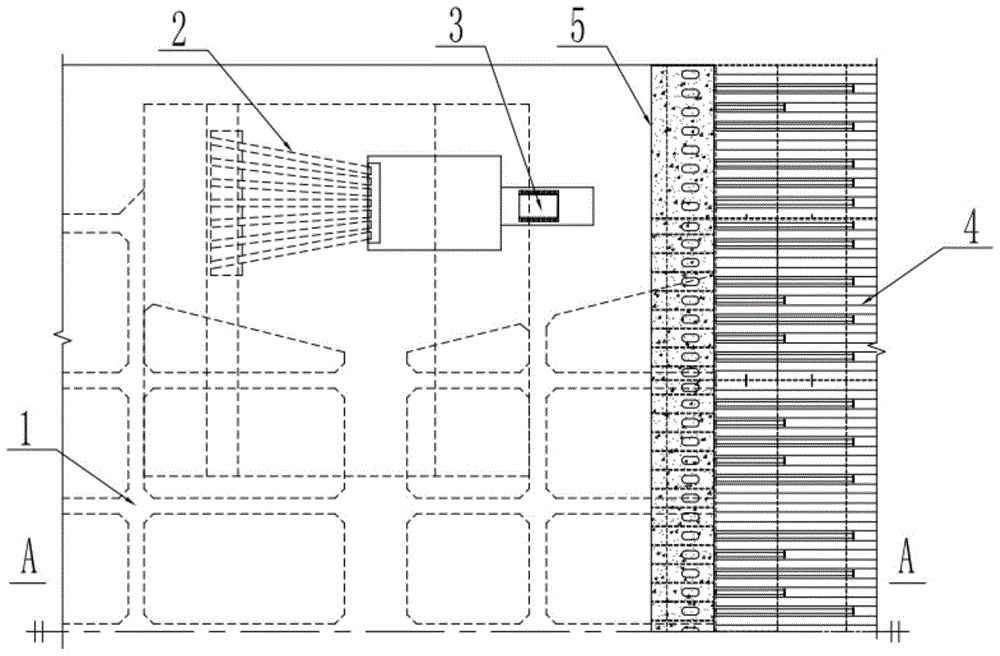
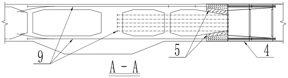
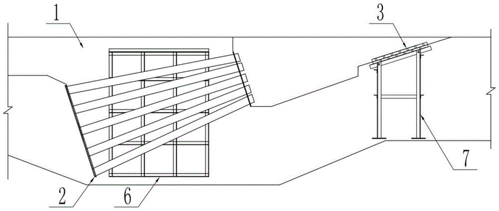
[0040] Such as Figure 1-4 As shown, a self-anchored suspension bridge anchored span cast-in-situ concrete box girder according to an embodiment of the present invention includes a concrete beam section 1, and a support skeleton 6 is arranged on the concrete beam section 1, and a support skeleton 6 is provided on the support skelet...


PUM


Abstract

The invention discloses a self-anchored suspension bridge anchor span cast-in-place concrete box beam construction method which includes the steps: mounting a bottom mould and a side mould; mounting a steel-concrete composite beam segment steel component; mounting a bottom plate binding reinforcement, a bottom plate prestressed pipeline and a prestressed reinforcement; mounting a cable rope anchor system; mounting a splay saddle or splay casting base bracket; mounting a web plate binding reinforcement, a web plate prestressed pipeline and a prestressed reinforcement; mounting an inner mould; casting and curing a concrete beam segment for the first time; mounting a top plate binding reinforcement, a top plate prestressed pipeline and a prestressed reinforcement; mounting a splay saddle or splay casting base; casting and curing the concrete beam segment for the second time; constructing a steel-concrete composite beam segment concrete structure; tensioning the prestressed reinforcements; removing a formwork. The construction method has the advantages that sub-projects are reasonably arranged, the cable rope anchor system and the like can be accurately positioned, construction of the steel-concrete composite beam segment is facilitated, construction quality is improved, the method is simple and convenient in construction, and construction period can be shortened.

Description

technical field [0001] The invention relates to the technical field of bridge construction, in particular to a self-anchored suspension bridge anchored span cast-in-situ concrete box girder and a construction method thereof. Background technique [0002] Self-anchored suspension bridge, as a flexible cable-suspension system, has become a competitive bridge type for small and medium-span bridges due to its beautiful structure, good economy, and strong adaptability to geological and terrain conditions. However, its structural force is complex, and the forces of towers, cables, and beams are highly coupled, and the nonlinear effect is significant. Among them, the main girder not only bears part of the dead load and live load of the bridge deck system, but also bears the horizontal force transmitted by the main cable. [0003] According to the type of material, main beams are generally divided into concrete stiffened beams and steel stiffened beams. With the development of rel...

Claims


Application Information

Patent Timeline
Patent Type & Authority Patents(China)
IPC IPC(8): E01D19/00E01D21/00E01D11/02
CPCE01D2/04E01D11/02E01D19/14E01D21/00E01D2101/28
Inventor 贾洪钱增志周大兴吴桐金
Owner CHINA RAILWAY CONSTR GROUP
Features
  • R&D
  • Intellectual Property
  • Life Sciences
  • Materials
  • Tech Scout
  • Unparalleled Data Quality
  • Higher Quality Content
  • 60% Fewer Hallucinations
Learn More