Bridge deck unit without transverse surface tension joints, bridge structure and its construction method

A bridge structure, no lateral technology, used in bridges, bridge parts, bridge construction, etc., can solve the problems of cracking, large lateral joints, affecting the durability of bridge decks, etc. Effect

Active Publication Date: 2016-06-08
HUNAN ZHONGLU HUACHENG BRIDGE TECH CO LTD
View PDF8 Cites 0 Cited by
  • Summary
  • Abstract
  • Description
  • Claims
  • Application Information

AI Technical Summary

Problems solved by technology

[0004] The technical problem to be solved by the present invention is to overcome the deficiencies and defects mentioned in the above background technology, replace ordinary concrete with ultra-high performance concrete, and at this time face the problem of joints, because the fibers at the wet joints are discontinuous, the joints The strength at the bridge deck is too low, and the transverse joints are often stressed, which leads to early cracking of the joints and affects the durability of the bridge deck; Bridge deck units without transverse surface tension joints that can be applied to steel-ultra-high performance concrete composite structures with low life-cycle cost, and the bridge deck units without transverse surface tension joints composed of the bridge deck units without transverse surface tension joints Seam bridge structure, also correspondingly provide a kind of simple process, convenient operation, fast construction speed, good economy when the bridge structure without transverse surface tension seam is applied in long-span girder bridge, cable-stayed bridge or suspension bridge Construction method

Method used


Image

  • Bridge deck unit without transverse surface tension joints, bridge structure and its construction method
  • Bridge deck unit without transverse surface tension joints, bridge structure and its construction method
  • Bridge deck unit without transverse surface tension joints, bridge structure and its construction method

Examples


Embodiment

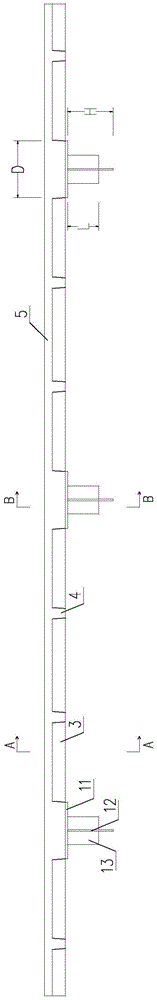
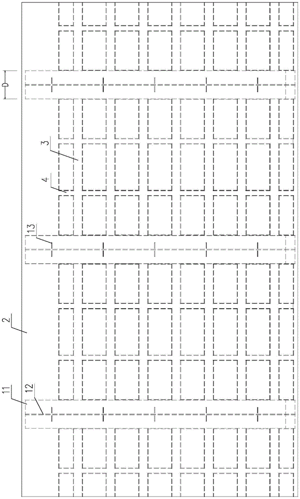
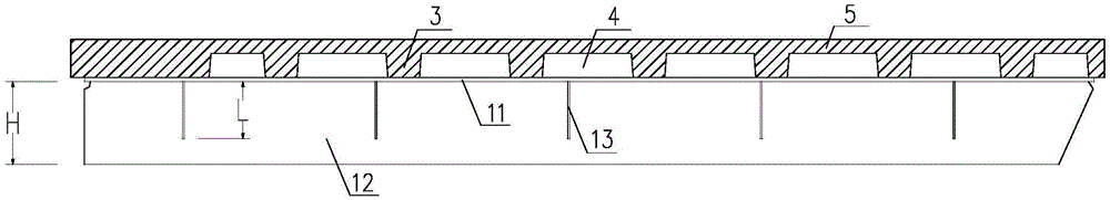
[0045] Such as Figure 1 to Figure 4 Shown, a bridge deck unit without transverse surface tension joints applicable to steel-ultra-high performance concrete composite structure of the present invention, the bridge deck unit mainly consists of diaphragm 1 of steel material and ultra-high performance concrete material The bridge deck 2 is integrally prefabricated; the diaphragm 1 includes an upper flange 11 and an upper web 12 fixed to each other. Such as figure 1 As shown, the upper flange 11 of the diaphragm 1 is pre-embedded in the bridge deck 2, and there is no transverse surface tension joint above the upper flange 11; the upper web 12 of the diaphragm 1 is arranged at intervals along the transverse direction of the bridge There are multiple upper vertical stiffeners 13 parallel to each other (see figure 1 with figure 2 ). The bridge deck 2 adopts a grid-like thin plate with longitudinal ribs 3 and transverse ribs 4 on the lower part (see figure 2 ). Both sides of t...


PUM


Abstract

The invention discloses a bridge deck unit without transverse surface tensioned joints. The bridge deck unit is mainly formed by integral prefabrication of diaphragm plates and a bridge deck slab. Upper flanges of the diaphragm plates are pre-embedded in the bridge deck slab, and the upper sides of the upper flanges are free of the transverse surface tensioned joints; a latticed thin plate provided with longitudinal ribs and transverse ribs is selected as the bridge deck slab, and two sides of the bridge deck slab are set to be connection portions and extend outwardly to form connection rebars. At least two bridge deck units, lower webs and longitudinal bridge steel beams are connected to from a bridge structure without the transverse surface tensioned joints, wherein the lower webs and the longitudinal bridge steel beams are positioned on the lower portions of the bridge deck units, and cast-in-situ joints are arranged on the upper sides of upper flanges of the longitudinal bridge steel beams; the connection rebars of every two adjacent bridge deck units are bound at the cast-in-situ joints. A construction method includes welding longitudinal bridge steel beam segments, welding shearing-force nails, erecting prefabricated bridge deck slab construction formworks, prefabricating the bridge deck units through casting, lifting the bridge deck units to the steel beam segments, welding the diaphragm plates and finally, casting the joints in situ to complete construction. The bridge deck unit has the advantages of light dead weight, high durability, good stress performance, low cost and the like.

Description

technical field [0001] The invention relates to a bridge deck unit, a bridge component and a construction method thereof, in particular to a bridge deck unit, a bridge component and a construction method applicable to a steel-ultra high-performance concrete composite structure. Background technique [0002] Cracking of concrete deck is one of the main problems of steel-concrete composite girder cable-stayed bridges. Although there are many causes of concrete bridge deck cracking, the essential reason lies in the steel-concrete composite girder structure and the material itself, that is, the concrete material has mechanical properties such as small crack resistance, low tensile strength, and obvious shrinkage and creep effects. At the same time, the composite girder deck and the lower steel girder are restrained by rigid connections, and the free deformation capacity is poor, which makes the concrete deck easily cracked under the action of external loads and effects. In the ...

Claims


Application Information

Patent Timeline
Patent Type & Authority Patents(China)
IPC IPC(8): E01D19/12E01D1/00E01D21/00
CPCE01D19/125E01D21/00
Inventor 邵旭东胡建华孔令方吴佳佳
Owner HUNAN ZHONGLU HUACHENG BRIDGE TECH CO LTD
Why Eureka
Try Eureka