
Multifunctional robot for drilling site

A field-used, multi-functional technology, applied to drilling equipment, drill pipes, drill pipes, etc., can solve problems such as insecurity and low automation, achieve long life, high safety, and reduce hidden dangers of accidents

Inactive Publication Date: 2015-04-29
CHINA PETROCHEMICAL CORP +1
View PDF5 Cites 19 Cited by
  • Summary
  • Abstract
  • Description
  • Claims
  • Application Information

AI Technical Summary

Problems solved by technology

[0002] At present, domestic oil drilling rigs mainly rely on pneumatic or hydraulic winches to lift and lower oil pipe strings, and most of them manually push the oil pipe strings from the pipe racks to the runway, which has a low degree of automation and unsafe factors.

Method used


Image

  • Multifunctional robot for drilling site
  • Multifunctional robot for drilling site
  • Multifunctional robot for drilling site

Examples


Embodiment 1

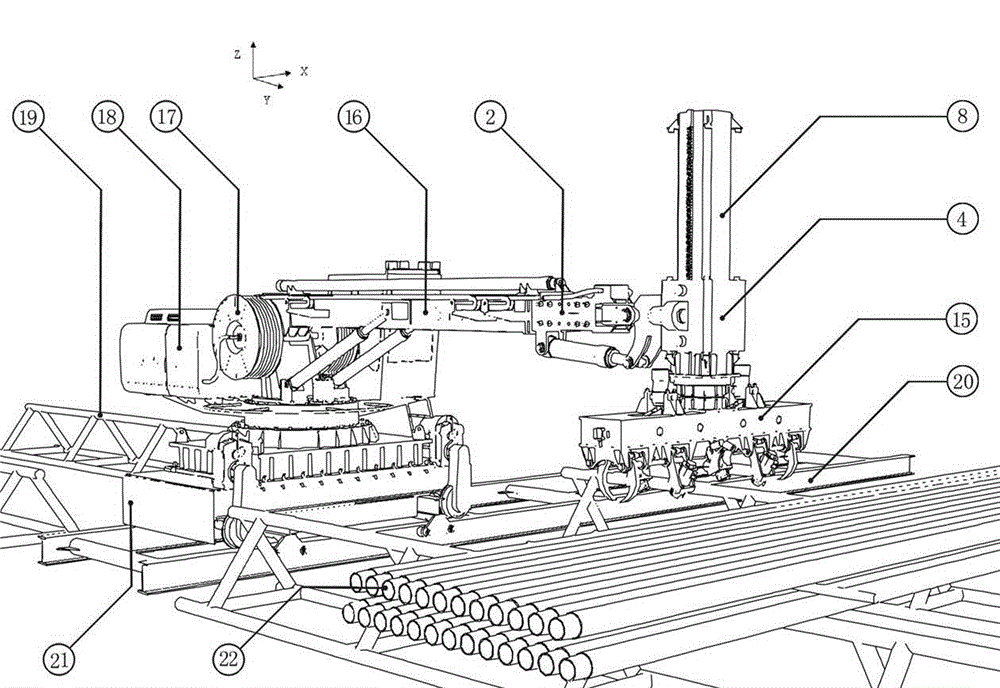
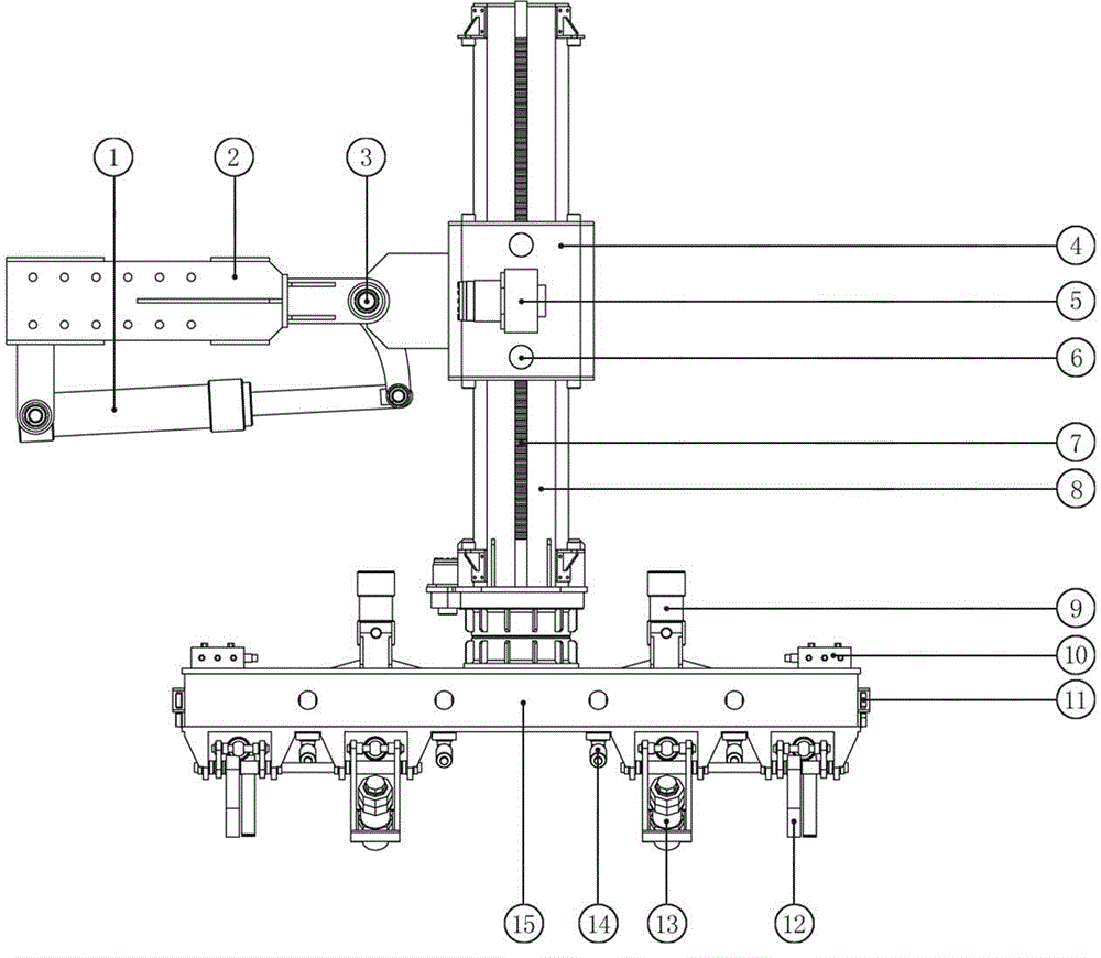
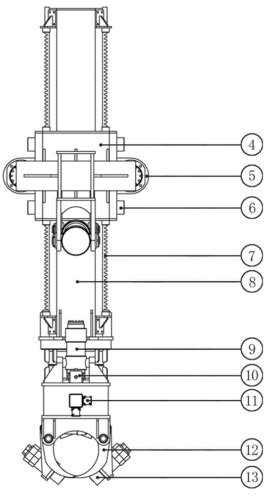
[0019] Reference attached Figure 1-4 , a kind of multifunctional robot for drilling site, including a crane 18 and an extension arm 16, the front end of the extension arm 16 is hinged with a ram cover 4 through a connecting sleeve 2, and the connecting sleeve 2 and the ram cover 4 are connected by a ram cover swing cylinder 1 and Form a rotation drive fit; the ram cover 4 is a hollow structure, the ram cover 4 is set outside the ram 8, the ram rack 7 is set on the ram 8, the ram rack 7 and the ram displacement hydraulic motor set on the ram cover 4 The speed reducer 5 and the ram rack brake 6 form a dynamic fit; the lower end of the ram 8 forms a rotational fit with the manipulator frame 15 through the turntable bearing; , Grabbing claws 12, friction wheels 13 and floating positioning rollers 14 are connected and driven by oil cylinders respectively.

[0020] Embodiment 1 is a basic embodiment of the present invention, which can complete the basic functions of grabbing, rota...

Embodiment 2

[0022] combined with Figure 1-4 , a kind of multifunctional robot for drilling site mainly consists of crane 18, walking track 20, extension arm 16, connection sleeve 2, ram cover 4, ram 8 and mechanical mobile phone frame 15 several major parts. Wherein: the connecting sleeve 2 is connected with the extension arm 16 through the standard connecting plate, and the hinge mandrel 3 and the ram cover swing cylinder 1 are installed between the ram cover 4 and the connecting cover 2 . The ram cover 4 is hollow, and is set on the outside of the ram 8, and the ram 8 forms a dynamic fit with the ram cover 4 through the ram rack 7. The end of the ram 8 is provided with a mechanical mobile phone frame 15, and the mechanical mobile phone frame 15 forms a rotation fit with the ram 8 through a turntable bearing driven by a hydraulic motor.

[0023] Four groups of evenly distributed floating positioning rollers 14 are arranged on the bottom surface of the mobile phone frame 15, each group ...


PUM


Abstract

The invention discloses a multifunctional robot for a drilling site. The multifunctional robot comprises a crane and a telescopic arm, wherein the front end of the telescopic arm is hinged to a ram sleeve by a connecting sleeve, the connecting sleeve and the ram sleeve are connected by a ram sleeve swinging oil cylinder to form the rotary driving fit, the ram sleeve is of a hollow structure, and sleeves the exterior of a ram, a ram rack is arranged on the ram, the ram rack is in movable fit with a ram displacement hydraulic motor speed reducer and a ram rack brake which are arranged on the ram sleeve, the lower end of the ram is in rotary fit with a manipulator machine frame through a rotary disc bearing, and a pipe grabbing gripper, a friction wheel and a floating positioning roller are arranged at the bottom surface of the manipulator bottom frame, and are connected and driven by an oil cylinder. The multifunctional robot has the advantages that the equipment, such as drill pipes, drill collars, casings and protecting pipes, required by the automatic conveying and the fetching and storage of a land petroleum drilling platform are realized, and the multifunctional robot can be widely applied to the field of automatic modification of land petroleum drilling machines and offshore drilling platforms.

Description

technical field [0001] The invention relates to the field of automatic mechanical devices for oil well site operations, in particular to a multifunctional robot for drilling sites, which can be widely used in the automation transformation of drilling and completion operation machinery on land oil drilling platforms. Background technique [0002] At present, domestic oil drilling rigs mainly rely on pneumatic or hydraulic winches to lift and lower oil pipe strings, and most of them are manually pushed from the pipe rack to the runway, which has a low degree of automation and unsafe factors. Contents of the invention [0003] One object of the present invention is to make up for the deficiencies of the prior art, and to provide a drilling system that realizes the automatic delivery and pick-up of drill pipes, drill jacks, casings, protective pipes and other management equipment required in the operation of onshore oil drilling platforms. Field-use multifunctional robot. [...

Claims


Application Information

Patent Timeline
IPC IPC(8): E21B19/15
CPCE21B19/155
Inventor 安庆宝李进付董怀荣李海营江正清曲刚
Owner CHINA PETROCHEMICAL CORP
Learn More