Method for estimating charge air cooler condensation storage with an intake oxygen sensor

A charge air cooling and oxygen sensor technology, which is applied in the control of coolant flow, the arrangement of the combination of cooling of the power unit, and the cooling of the engine, etc., can solve the problems of unstable combustion of the engine, etc.

Active Publication Date: 2015-04-29
FORD GLOBAL TECH LLC
View PDF4 Cites 1 Cited by
  • Summary
  • Abstract
  • Description
  • Claims
  • Application Information

AI Technical Summary

Problems solved by technology

Therefore, engine misfire and/or u

Method used


Image

  • Method for estimating charge air cooler condensation storage with an intake oxygen sensor
  • Method for estimating charge air cooler condensation storage with an intake oxygen sensor
  • Method for estimating charge air cooler condensation storage with an intake oxygen sensor

Examples


Embodiment Construction

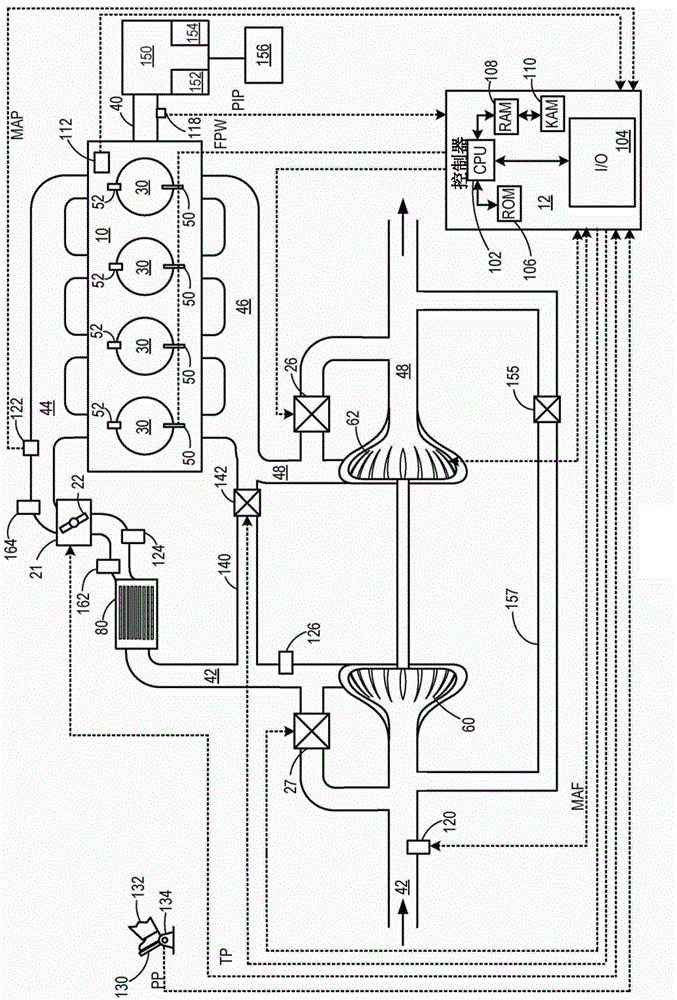
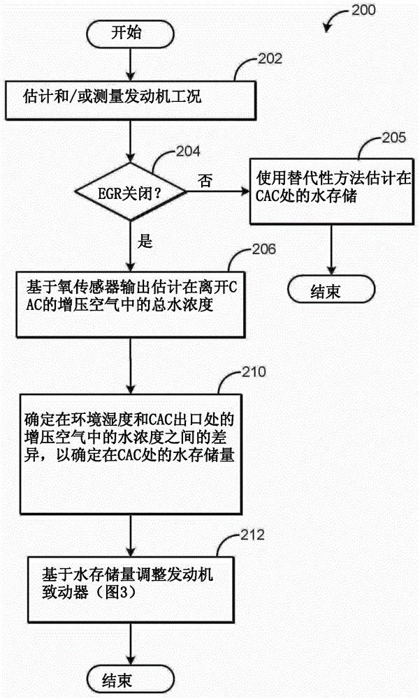
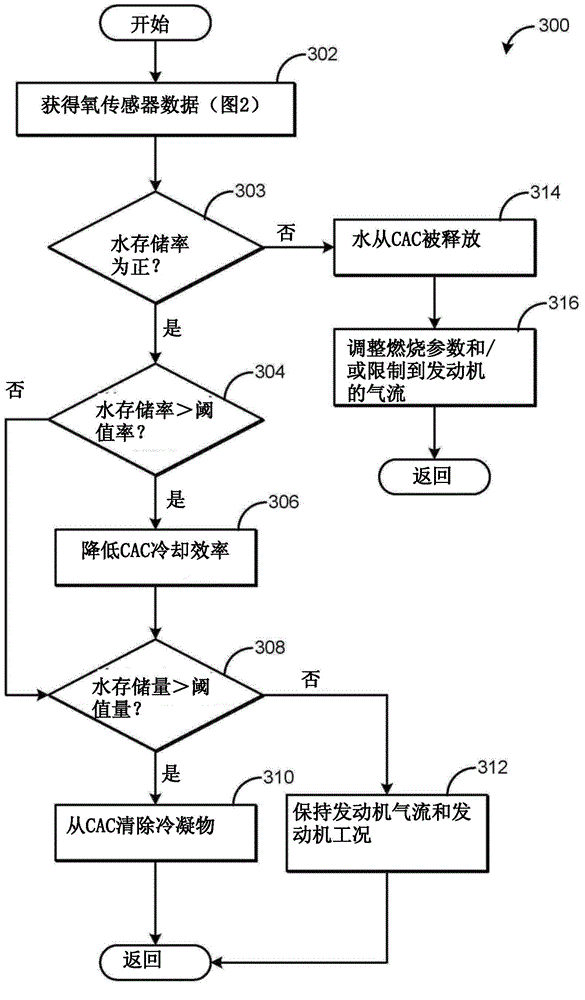
[0010] The following description refers to methods for estimating figure 1 Systems and methods for water storage in a charge air cooler (CAC) within an engine system of the system. A first oxygen sensor may be placed at the outlet of the CAC. In one example, the oxygen sensor may be a variable voltage intake oxygen sensor operable between a variable voltage (VVs) mode and a fundamental mode. figure 2 A method for operating a first oxygen sensor determining water storage at a CAC is shown. In particular, the water storage level, or the amount of water accumulated within the CAC, may be determined based on the output of the first oxygen sensor and the ambient humidity. The first oxygen sensor may be distinct from the second intake oxygen sensor placed within the intake manifold that determines EGR flow. as in image 3 As shown in , the engine controller can adjust engine operation based on the amount of water storage. Adjusting engine operation may include adjusting engine...


PUM


Abstract

Methods and systems are provided for estimating water storage in a charge air cooler (CAC). In one example, an amount of water accumulating in the CAC may be based on an output of an oxygen sensor positioned downstream of the CAC and ambient humidity. Further, engine actuators may be adjusted to purge condensate from the CAC and/or reduce condensate formation based on the amount of water inside the CAC.

Description

technical field [0001] The present invention relates to a method of estimating charge air cooler condensate storage using an intake oxygen sensor. Background technique [0002] Turbocharged and supercharged engines can be configured to compress ambient air entering the engine in order to increase power. Compression of air can result in an increase in air temperature, therefore, an intercooler or charge air cooler (CAC) can be used to cool the heated air, increasing its density and further increasing the potential power of the engine. Condensate may form in the CAC when the ambient air temperature drops, or during humid or rainy weather conditions when intake air is cooled below the water dew point. Condensate can collect at the bottom of the CAC or in the internal channels and cool the turbulators. Under certain airflow conditions, condensate can leave the CAC and enter the engine's intake manifold as water droplets. If the engine picks up too much condensate, engine misf...

Claims


Application Information

Patent Timeline
IPC IPC(8): F02P5/00F02D41/00F01P7/02F02D43/00B60K11/08F02B29/04
CPCF02B29/04F02B29/0468F02D41/0007F02D41/144F02D41/1454F02D2200/0418Y02T10/12F02D41/1458F02D43/02F02D43/04
Inventor G·苏妮拉D·J·斯泰尔斯J·A·海蒂奇M·亚伯拉罕
Owner FORD GLOBAL TECH LLC
Why Eureka
Try Eureka