Bilateral dislocation differential confocal element parameter measuring method

A technology of component parameters and measurement methods, applied in the direction of testing optical properties, etc.

Active Publication Date: 2015-04-29
BEIJING INSTITUTE OF TECHNOLOGYGY
View PDF6 Cites 40 Cited by
  • Summary
  • Abstract
  • Description
  • Claims
  • Application Information

AI Technical Summary

Problems solved by technology

However, since the convergent objective lens 4 of the confocal element parameter measurement device must satisfy the objective lens working distance and working wavelength required for measur

Method used


Image

  • Bilateral dislocation differential confocal element parameter measuring method
  • Bilateral dislocation differential confocal element parameter measuring method
  • Bilateral dislocation differential confocal element parameter measuring method

Examples


Embodiment 1

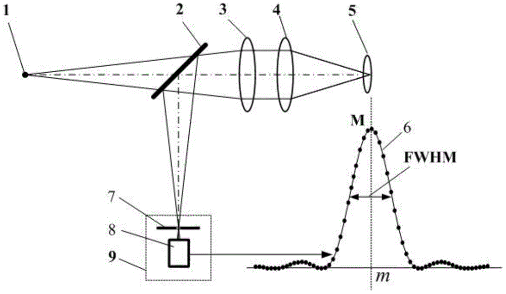
[0092] to combine figure 2 , the specific steps of using the method of the present invention to measure the radius of curvature of the surface of the spherical element are as follows:

[0093] Step 1. Place the test piece 5 behind the converging objective lens 4, adjust the test piece 5 so that its optical axis is on the same optical axis as the measurement beam, and part of the light is reflected when it hits the surface of the test piece 5;

[0094] Step 2: Move the measured object 5 to scan along the optical axis, and the confocal detection system 9 detects the corresponding vertex position Z 1 The spherical top confocal response data set 14;

[0095] Step 3: Continue to move the DUT 5 along the optical axis, and detect the corresponding sphere center position Z through the confocal detection system 9 again 2 The spherical center confocal response data set 18;

[0096] Step 4. Perform bilateral intersection and subtraction processing on the spherical top confocal respon...

Embodiment 2

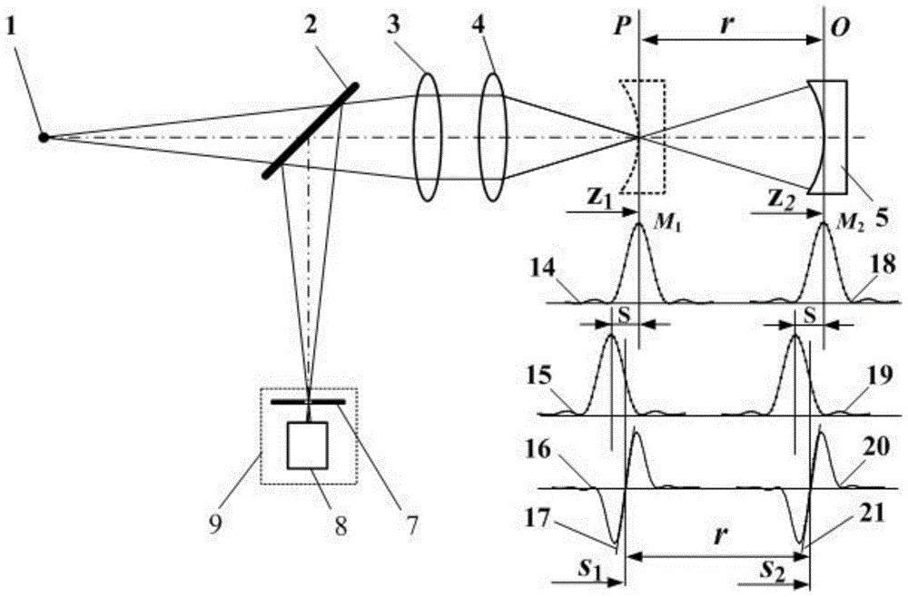
[0100] combine image 3 , utilize the method of the present invention to measure lens thickness concrete steps as follows:

[0101] Step 1, place the measured ball lens 22 behind the converging objective lens 4, adjust the measured ball lens 22 so that its optical axis and the measuring beam have the same optical axis, and the light beam converges near the left apex of the measured ball lens 22;

[0102] Step 2: Move the measured ball lens 22 to scan along the optical axis, and the confocal detection system 9 detects the position Z corresponding to the left apex 1 The left apex of the confocal response data set 23;

[0103] Step 3: Continue to translate the measured ball lens 22 along the optical axis, and detect the corresponding right apex position Z through the confocal detection system 9 again 2 The right vertex of the confocal response data set 27;

[0104] Step 4. Perform bilateral intersection and subtraction processing on the left apex confocal response data set 23 ...

Embodiment 3

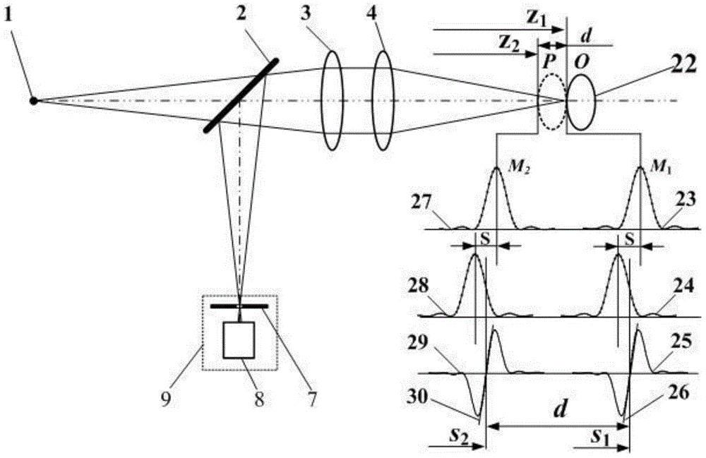
[0109] The ball lens 22 to be tested is selected as a GCL-0101 K9 plano-convex lens, and its known parameters are: nominal refractive index n 1 = 1.51466, nominal thickness d = 4.000mm, radius of curvature r 1 =∞, r 2 =90.7908mm.

[0110] Measuring system, the maximum light aperture of the measuring mirror used is D=9.6mm, and the focal length is f 1 '=35mm, the aperture is R=4.5mm. The length measurement is carried out by using the nanoscale resolution grating to translate the length measurement guide rail device.

[0111] combine Figure 4 , the specific steps of measuring the refractive index of the lens by the method of the present invention are as follows:

[0112] Step 1: Place the measured ball lens 22 behind the converging objective lens 4, and adjust the converging objective lens 4 so that it has the same optical axis as the measuring beam. Place the plane reflector 31 behind the measured ball lens 22, adjust the plane reflector 31 so that it is perpendicular to...


PUM

PropertyMeasurementUnit
Caliberaaaaaaaaaa
Focal lengthaaaaaaaaaa
Apertureaaaaaaaaaa

Abstract

The invention belongs to the technical field of optical imaging and detecting and relates to a bilateral dislocation differential confocal element parameter measuring method. The method includes the steps that dislocation differential subtracting processing is conducted on the two sides of a confocal axial characteristic data set measured by the starting points and the ending points of all various size parameters including the curvature radius, the lens thickness, the refractive rate, the focal distance and the interval, and therefore the positioning precision of the starting points and the ending points of the size parameters is improved, and the measuring precision of optical elements of the curvature radius, the lens thickness, the refractive rate, the focal distance, the interval and the like is improved. According to the bilateral dislocation differential confocal element parameter measuring method, due to the fact that two sections of data, close to the position of the full width at half maximum and very sensitive to axial displacement, of a confocal characteristic curve are used for conducting the dislocation differential subtracting processing, the position, calculated by the data sections, of the extreme point of the confocal characteristic curve is more sensitive and more accurate than the position, calculated through an existing confocal characteristic curve top fitting method, of the extreme point of the confocal characteristic curve, according to the result of the bilateral dislocation differential confocal element parameter measuring method, under the condition that the confocal element parameter system structure is not changed, the axial focusing capability, the signal-to-noise ratio and the like of the system can be obviously improved.

Description

technical field [0001] The invention relates to a method for measuring the parameters of a bilateral misalignment differential confocal element, belonging to the technical field of precision measurement of optical element parameters. technical background [0002] In the field of optical component parameter measurement, due to the influence of the diffraction limit, the focusing and positioning ability of the measured focused beam is restricted, and it has become a technical bottleneck for high-precision measurement of parameters such as component curvature radius, lens thickness, refractive index, focal length and spacing. [0003] In fact, the radius of curvature of the element, the thickness of the lens, the refractive index of the lens, the focal length of the lens and the distance between the mirror groups are all parameters of the size and length. At present, the accuracy of laser interferometric length measuring instrument and nanoscale grating length measuring instrum...

Claims


Application Information

Patent Timeline
IPC IPC(8): G01M11/02
Inventor 赵维谦邱丽荣
Owner BEIJING INSTITUTE OF TECHNOLOGYGY
Why Eureka
Try Eureka