
Dynamic load test bench for agricultural machinery rotary tillage components

An agricultural machinery and dynamic load technology, which is applied in the testing of mechanical components, testing of machine/structural components, measuring devices, etc., can solve problems such as poor interchangeability and versatility of working parts, limited torque of test data, single load test, etc. , achieve the effect of shortening response time, saving maintenance cost and improving adjustment accuracy

Inactive Publication Date: 2017-02-22
CHONGQING UNIV OF TECH
View PDF6 Cites 0 Cited by
  • Summary
  • Abstract
  • Description
  • Claims
  • Application Information

AI Technical Summary

Problems solved by technology

The soil-contacting parts test device based on the soil tank test rig that has been reported at present mainly has the following deficiencies: 1. The soil tank test rig and its trolley are relatively large in size and specifications, and realize different functions (such as rotary tillage, leveling, compaction) etc.), the trolley system is relatively independent; 2. Most of the test devices have a single load test, and the test data is mostly limited to torque; 3. Most of the test devices are aimed at single-roller structures, and are limited to single-roller single-knife or multi-knife test research; 4. Most test devices are limited to specific tests, and the interchangeability and versatility of working parts are poor

Method used


Image

  • Dynamic load test bench for agricultural machinery rotary tillage components
  • Dynamic load test bench for agricultural machinery rotary tillage components
  • Dynamic load test bench for agricultural machinery rotary tillage components

Examples


Embodiment Construction

[0038] Below in conjunction with accompanying drawing and example the present invention is described in further detail.

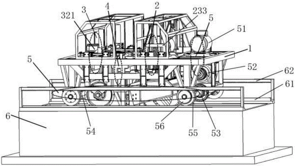
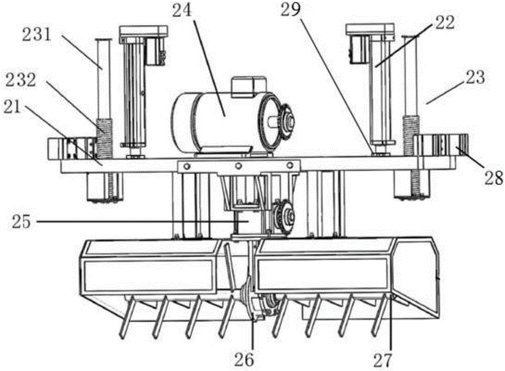
[0039] see figure 1 A test bench for dynamic load testing of agricultural machinery rotary tillage components, including a soil tank 6 and a trolley, the trolley including a trolley frame 1, a rotary tillage system 2, a soil compaction system 3, a soil leveling system 4 and a walking system 5. The rotary tillage system 2 is installed on the trolley frame 1, and the distance between the rotary tillage system 2 and the front end of the trolley frame 1 is smaller than the distance between the rotary tillage system 2 and the rear end of the trolley frame 1. The soil compaction system 3 is installed on the trolley frame 1, and the distance between the soil compaction system 3 and the front end of the trolley frame 1 is greater than the distance between the soil compaction system 3 and the rear end of the trolley frame 1. The soil leveling system 4 is installed ...


PUM


Abstract

The invention discloses a dynamic load testing testbed for an agricultural mechanical rotary cultivation part. The dynamic load testing testbed comprises a soil groove and a trolley, wherein the trolley comprises a trolley rack, a rotary cultivation system, a soil compaction system, a soil leveling system and a walking system, the rotary cultivation system is installed at the front end of the trolley rack, the soil compaction system is installed at the rear end of the trolley rack, the soil leveling system is installed on the trolley rack and located between the rotary cultivation system and the soil compaction system, and the walking system is installed on the trolley rack. The testbed represents operation of the rotary cultivation part based on the soil groove and tests dynamic load of the rotary cultivation part. The dynamic load testing testbed has the advantages that the dynamic load testing testbed is not limited by seasons and farming seasons, can conduct real-time recovery processing on soil according to different demands, is good in testing repeatability, is not influenced by outside climate and natural conditions and the like, and can provide data support for theoretical research and design improvement of coil cultivation parts on the basis that a large number of resources are saved.

Description

technical field [0001] The invention belongs to the technical field of agricultural machinery testing, and in particular relates to a dynamic load testing test bench for agricultural machinery rotary tillage components. Background technique [0002] Soil tillage components are the core components of agricultural machinery, and their soil cutting performance directly affects the energy consumption and farming efficiency of agricultural machinery. Soil tillage components are mainly subjected to complex and randomly changing loads from the plow layer soil. Due to excessive resistance, the soil tillage components often lead to short service life, and even bending and fracture. Therefore, real-time testing of the dynamic load of soil tillage components and the study of their stress characteristics and laws during the tillage process will provide important test data and technical means for the design, selection and failure mode analysis of soil tillage components. It can provide ...

Claims


Application Information

Patent Timeline
Patent Type & Authority Patents(China)
IPC IPC(8): G01M13/00
Inventor 许洪斌刘妤梁举科杨岩徐涛金陈亚洁
Owner CHONGQING UNIV OF TECH
Learn More