
Self-cleaning vacuum treatment chamber

A vacuum treatment and self-cleaning technology, which is applied to electrical components, semiconductor/solid-state device manufacturing, circuits, etc., can solve problems such as low efficiency, achieve the effect of improving service life and saving costs

Inactive Publication Date: 2015-04-29
ADVANCED MICRO FAB EQUIP INC CHINA
View PDF3 Cites 5 Cited by
  • Summary
  • Abstract
  • Description
  • Claims
  • Application Information

AI Technical Summary

Problems solved by technology

However, such a cleaning method must completely separate the manufacturing process from the cleaning process, and the vacuum processing chamber must move the substrate out of the chamber after the substrate processing is performed for special cleaning treatment
This cleaning method is less efficient

Method used


Image

  • Self-cleaning vacuum treatment chamber
  • Self-cleaning vacuum treatment chamber
  • Self-cleaning vacuum treatment chamber

Examples


Embodiment Construction

[0022] The specific embodiments of the present invention will be described below in conjunction with the accompanying drawings.

[0023] This article will describe the present invention in conjunction with a plasma processing chamber (typically an etching tool). However, those skilled in the art should understand that the present invention is applicable to plasma etching equipment, chemical vapor deposition equipment, MOCVD equipment and the like.

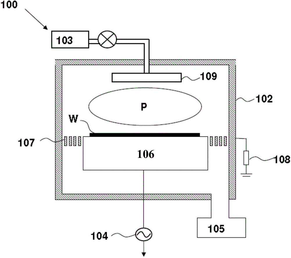
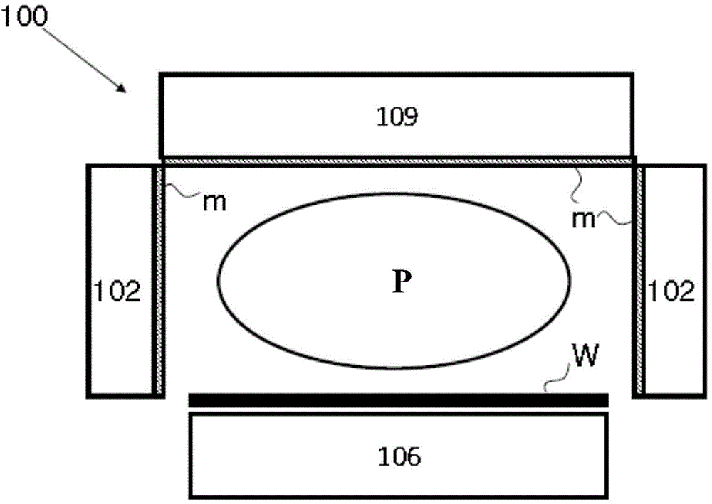
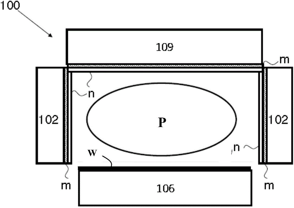
[0024] figure 1 is a schematic diagram of the structure of the plasma processing chamber. The plasma processing chamber 100 has a processing chamber 102 which is substantially cylindrical and has substantially vertical side walls. The upper electrode 109 and the lower electrode are arranged parallel to each other in the processing chamber 102 . Typically, the area between the upper electrode 109 and the lower electrode is the processing area P where high frequency energy will be developed to ignite and sustain the plasma. A subs...


PUM

PropertyMeasurementUnit
thicknessaaaaaaaaaa
thicknessaaaaaaaaaa
thicknessaaaaaaaaaa

Abstract

The invention provides a self-cleaning vacuum treatment chamber which comprises a chamber body, wherein a substrate is placed in the chamber body for processing, and a titanium dioxide coating is arranged on an internal area of the chamber body. The titanium dioxide coating is used for removing a polymer pollution layer generated in the chamber body. According to the vacuum treatment chamber and a self-cleaning method of the chamber, the polymer pollution layer in the chamber body can be effectively removed, and is difficult to deposit on the surface of an internal wall of the chamber body, the deposited polymer pollution layer can be degraded, and the adhesiveness of the deposited polymer pollution layer is reduced.

Description

technical field [0001] The invention relates to the field of semiconductor manufacturing, in particular to a self-cleaning vacuum processing chamber. Background technique [0002] After the vacuum processing chamber performs the process on the substrate, excess solid by-product deposit pollution (such as hydrocarbon-containing organic matter or metal and its compounds, etc.) will be formed inside the reaction chamber. These deposits are deposited inside the reaction chamber ( Especially on the inner wall of the cavity), resulting in process drift and performance degradation, and it is easy to form impurities such as particles on the surface of the substrate during the subsequent process, and these impurities will affect the subsequent process. Therefore, during use, the vacuum processing chamber needs to be cleaned to remove deposits inside the reaction chamber, thereby improving process quality and prolonging the service life of the vacuum processing chamber. [0003] In t...

Claims


Application Information

Patent Timeline
Patent Type & Authority Applications(China)
IPC IPC(8): H01L21/00H01L21/67
Inventor 张力贺小明李俊良倪图强
Owner ADVANCED MICRO FAB EQUIP INC CHINA
Learn More