MOSFET (metaloxide semiconductor field effect transistor) structure and manufacturing method thereof

A manufacturing method and substrate technology, applied in semiconductor/solid-state device manufacturing, semiconductor devices, electrical components, etc., can solve problems affecting device performance, increase barrier height, optimize device performance, reduce number and probability Effect

Active Publication Date: 2015-04-29
INST OF MICROELECTRONICS CHINESE ACAD OF SCI
View PDF3 Cites 0 Cited by
  • Summary
  • Abstract
  • Description
  • Claims
  • Application Information

AI Technical Summary

Problems solved by technology

[0003] As the voltage between the source and drain increases, the electric field where the carriers in the pinch-off region is also increases, so the electrons can obtain higher speed and greater energy, and generate a certain number of hot carriers. When the electric field in the pinch-off region increases to a certain extent, these hot carriers have a certain probability to cross the barrier between the channel and the gate dielectric layer and enter the gate dielectric layer, thereby introducing defects and traps in the gate dielectric layer , affecting device performance

Method used


Image

  • MOSFET (metaloxide semiconductor field effect transistor) structure and manufacturing method thereof
  • MOSFET (metaloxide semiconductor field effect transistor) structure and manufacturing method thereof
  • MOSFET (metaloxide semiconductor field effect transistor) structure and manufacturing method thereof

Examples


Embodiment Construction

[0025] In order to make the object, technical solution and advantages of the present invention clearer, the embodiments of the present invention will be described in detail below with reference to the accompanying drawings.

[0026] Embodiments of the present invention are described in detail below, examples of which are shown in the drawings, wherein the same or similar reference numerals designate the same or similar elements or elements having the same or similar functions throughout. The embodiments described below by referring to the figures are exemplary only for explaining the present invention and should not be construed as limiting the present invention.

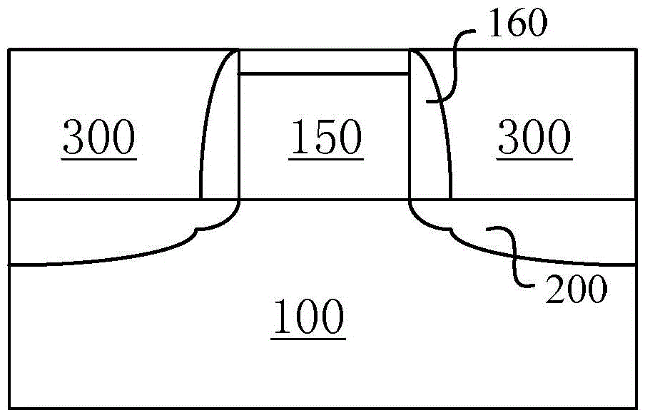
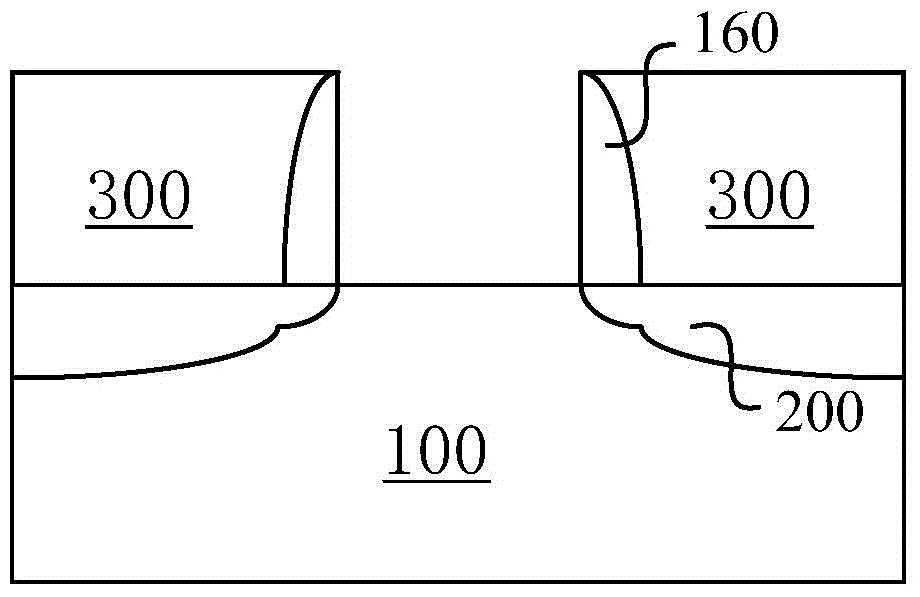
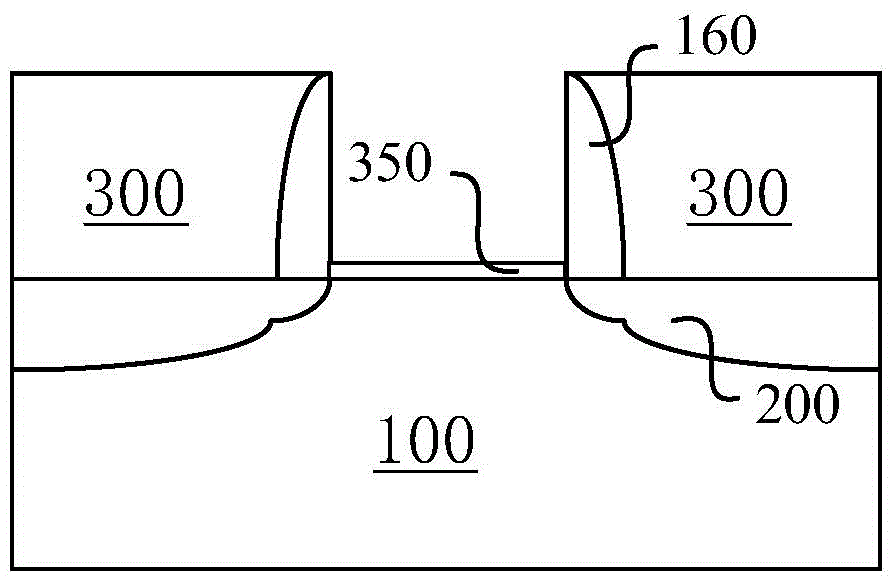
[0027] see Figure 7 , the present invention provides an asymmetric MOSFET structure, comprising: a substrate 100; a gate stack 500 located above the substrate 100; source and drain regions 200 located in the substrate on both sides of the gate stack 500 ; the spacer 160 on both sides of the gate stack 500 ; the in...


PUM


Abstract

Provided in the present invention is an MOSFET manufacturing method comprising: a. providing a substrate, a drain region, a dummy gate stack layer, an interlayer dielectric layer, and a sidewall; b. removing the dummy gate stack layer to form a dummy gate gap and forming an oxide layer on the substrate in the dummy gate gap; c. covering a photoresist at a side of a drain end of the semiconductor structure and exposing the oxide layer in proximity to a source end in the dummy gate gap; d. anisotropic etching the substrate and the oxide layer that are not covered by the photoresist, thus forming a gap; e. removing the photoresist and depositing a transition barrier layer in the gap until the transition barrier layer is in flush with the oxide layer; f. etching the semiconductor structure and removing the oxide layer to expose a groove surface; and, g. depositing a gate electrode stack layer in the dummy gate gap. Per the method provided in the present invention, hot-carrier effect is effectively suppressed while component performance is optimized.

Description

technical field [0001] The invention relates to a MOSFET structure and a manufacturing method thereof. More particularly, it relates to a MOSFET structure for reducing the number of hot electrons in a channel near the drain and a method of manufacturing the same. technical background [0002] When the MOSFET is in the saturation region, the channel inversion layer is partially pinched off, that is, the inversion carrier concentration on the channel surface near the drain end is very small, and the resistance is large. According to the series voltage division relationship, the voltage in the channel region is mostly Falling on the pinch-off region, a large electric field is generated in the pinch-off region. When the anti-type carriers in the channel region move to the boundary of the pinch-off region under the action of the electric field, they will be accelerated by the electric field of the pinch-off region, and will be quickly swept to the drain end. During this process,...

Claims


Application Information

Patent Timeline
Patent Type & Authority Applications(China)
IPC IPC(8): H01L21/336H01L29/78H01L29/06
CPCH01L29/1054H01L29/66545H01L29/7833H01L29/66477H01L29/06H01L29/78
Inventor 李睿尹海洲刘云飞
Owner INST OF MICROELECTRONICS CHINESE ACAD OF SCI
Why Eureka
Try Eureka