Screen mesh array conducting film, solar cell and preparation method thereof
A solar cell and conductive film technology, applied in circuits, electrical components, semiconductor devices, etc., can solve the problems of no benefit to the industry and high cost of silver materials, and achieve the effect of reducing production costs, high conductivity, and reducing dosage
- Summary
- Abstract
- Description
- Claims
- Application Information
AI Technical Summary
Problems solved by technology
Method used
Image
Examples
Embodiment 1
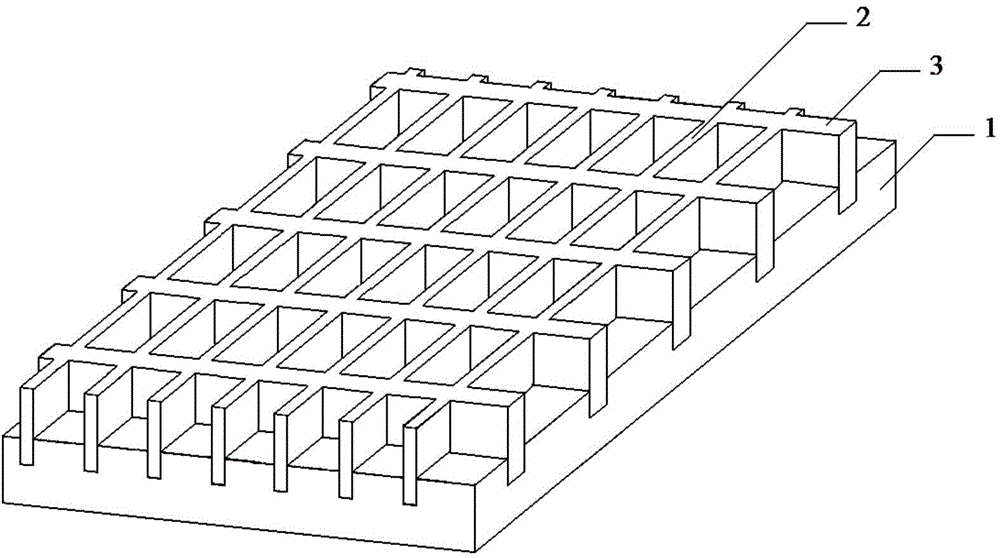
[0044] see figure 1 , figure 1 It is a structural schematic diagram of Embodiment 1 of the screen array conductive film of the present invention.
[0045] In Embodiment 1, the present invention provides a wire mesh array conductive film, the wire mesh array conductive film includes an optical film 1 and a conductive metal mesh, and the conductive metal mesh is arranged on either side of the optical film 1 , the conductive metal mesh includes a horizontal metal wire 2 and a vertical metal wire 3, and the horizontal metal wire 2 and the vertical metal wire 3 both include a high-conductivity metal core, and the outer surface of the high-conductivity metal core is coated with a low melting point metal layer.
[0046] It is worth noting that, figure 1 The grid of the conductive metal mesh is rectangular. However, according to the needs of battery manufacturers or users and other reasons, the grid can also be set to be honeycomb, circular, rectangular, square, polygonal and va...
Embodiment 2
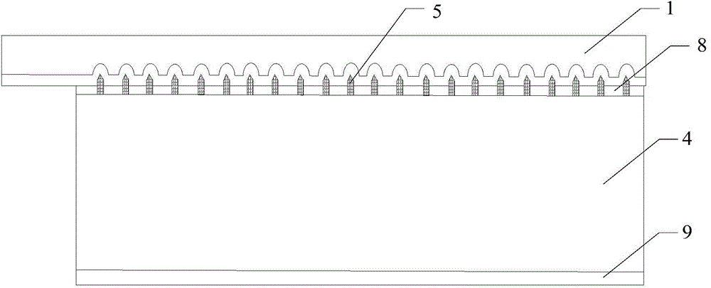
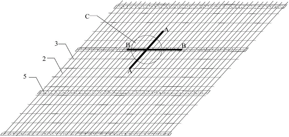
[0063] see figure 2 , image 3 , Figure 4 , Figure 5 , Image 6 , Figure 7 and Figure 8 , figure 2 It is a structural schematic diagram of solar cell embodiment 2 of the present invention; image 3 for figure 2 Schematic diagram of the structure of the middle conductive metal mesh in contact with the auxiliary grid line; Figure 4 for image 3 Schematic diagram of the enlarged structure of part C in middle; Figure 5 for image 3 A schematic diagram of the cross-sectional structure of A-A; Image 6 for image 3 Schematic diagram of the cross-sectional structure of B-B in the middle; Figure 7 for figure 2 Schematic diagram of the cross-sectional structure of the wire mesh array conductive film; Figure 8 for figure 2 Schematic diagram of the cross-sectional structure of a crystalline silicon cell without busbars in the middle.
[0064] In order to achieve the above object, Embodiment 2 of the present invention also provides a solar cell, which include...
Embodiment 3
[0071] see Figure 9-Figure 14 , Figure 9 It is a schematic flow chart of Embodiment 3 of the preparation method of the solar cell of the present invention; Figure 10-Figure 14 for Figure 9 The structural schematic diagram of each step of the preparation method of the solar cell shown.
[0072] In order to achieve the above object, Embodiment 3 of the present invention also provides a method for preparing a solar cell, the method comprising the following steps:
[0073] Step S10, preparing a wire mesh array conductive film (see Figure 10 );
[0074] The wire mesh array conductive film in the present invention includes an optical film 1 and a conductive metal mesh, the conductive metal mesh is arranged on either side of the optical film, the conductive metal mesh includes a horizontal metal wire and a vertical metal wire, so Both the horizontal metal wire and the vertical metal wire include a high-conductivity metal core 6 , and the outer surface of the high-conductivi...
PUM
| Property | Measurement | Unit |
|---|---|---|
| Radial thickness | aaaaa | aaaaa |
| Radial width | aaaaa | aaaaa |
| Radial width | aaaaa | aaaaa |
Abstract
Description
Claims
Application Information
 - R&D
- Intellectual Property
- Life Sciences
- Materials
- Tech Scout
- Unparalleled Data Quality
- Higher Quality Content
- 60% Fewer Hallucinations
Browse by: Latest US Patents, China's latest patents, Technical Efficacy Thesaurus, Application Domain, Technology Topic, Popular Technical Reports.
© 2025 PatSnap. All rights reserved.Legal|Privacy policy|Modern Slavery Act Transparency Statement|Sitemap|About US| Contact US: help@patsnap.com


