Novel ultra-wide frequency band radiating element and multi-band antenna comprising same

A radiating element and wide-band technology, applied in the field of multi-frequency antennas, can solve the problems of coupling and mutual blocking of different frequency bands, low height of high-frequency radiating elements, etc., and achieve the effect of reducing blocking effect, reducing mutual coupling, and excellent radiation performance.

Inactive Publication Date: 2015-04-29
GUANGDONG HUISU TELECOMM TECH
View PDF5 Cites 1 Cited by
  • Summary
  • Abstract
  • Description
  • Claims
  • Application Information

AI Technical Summary

Problems solved by technology

In order to send and receive multi-band signals at the same time, the designer has developed a multi-frequency antenna. At present, the typical technology of multi-frequency antennas in the industry is the deformation of the radiation unit of the binary array antenna or the form of a conventional symmetrical vibrator, and the size is relatively high, especially for low-frequency radiation. Due to its high height, the height of the high-frequency radiation unit is relatively low, resulting in serious coupling and mutual shielding between different frequency bands, resulting in various defects in the comprehensive index of the antenna

Method used


Image

  • Novel ultra-wide frequency band radiating element and multi-band antenna comprising same
  • Novel ultra-wide frequency band radiating element and multi-band antenna comprising same
  • Novel ultra-wide frequency band radiating element and multi-band antenna comprising same

Examples


Embodiment Construction

[0018] The present invention will be further described below in conjunction with specific embodiments and drawings.

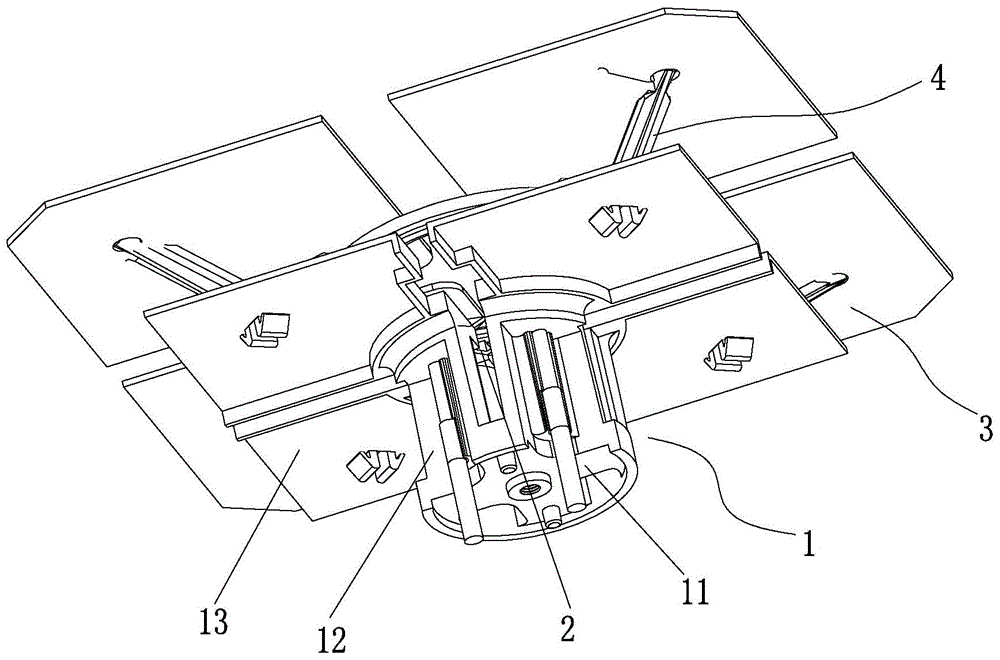
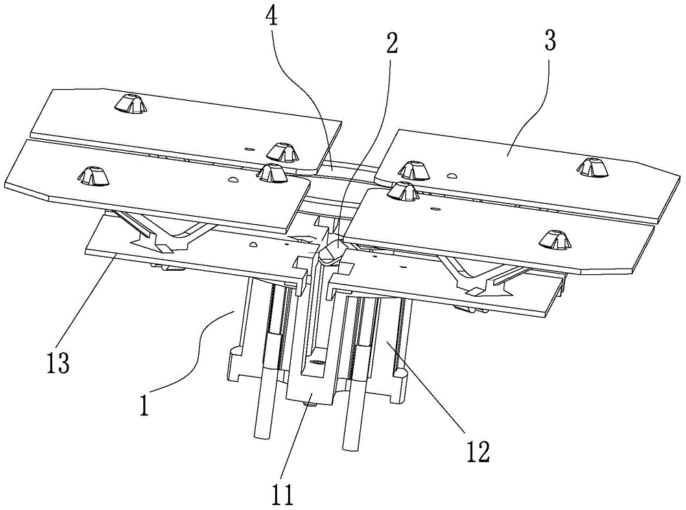
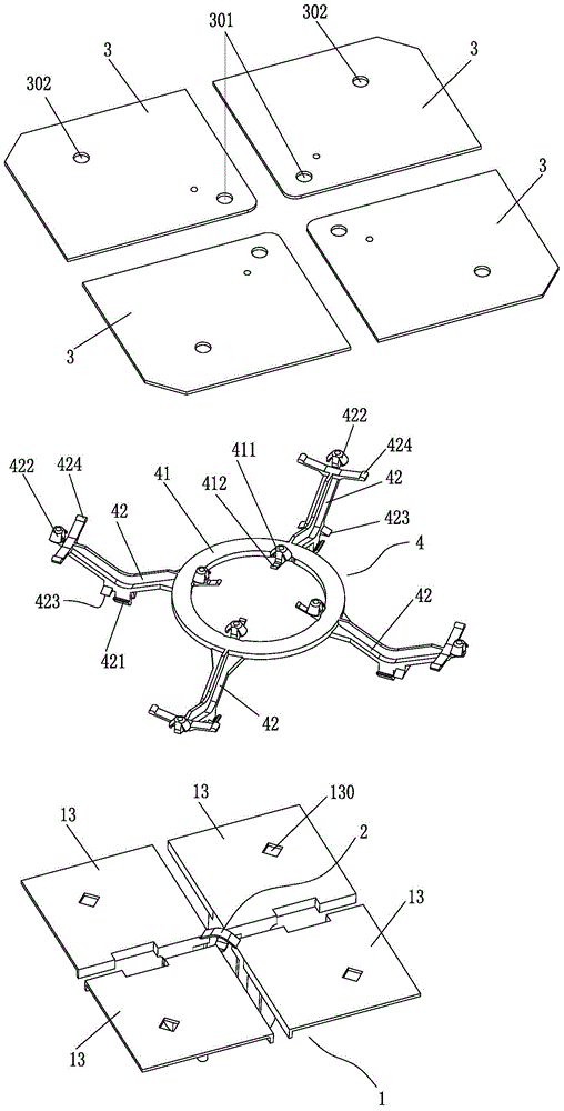
[0019] Such as Figure 1-Figure 4 As shown, a new type of ultra-wideband radiating unit according to the present invention, wherein: the ultra-wideband radiating unit includes a feeder 1, a feeder 2 and a main radiator 3, wherein the feeder 1 has A base 11, four discontinuous supports 12 extending vertically upward from the base 11 (supports 12 are evenly distributed in the circumferential direction), and a feeder plate 13 respectively formed outside the upper end of each support 12; Two of the support bodies 12 are outwardly convex arc-shaped, and the other two are inwardly concave arc-shaped; the upper ends of each two opposing support bodies 12 are connected with a feeder piece 2, two feeders The fins 2 are arranged in a crossed manner and do not contact each other; a main radiating fin 3 is respectively provided above each of the power feed plates 13, and the...


PUM


Abstract

The invention relates to the technical field of antenna equipment, in particular to a novel ultra-wide frequency band radiating element. The ultra-wide frequency band radiating element comprises a feed body, feed pieces and main radiation pieces, wherein the feed body comprises a base, four disconnected supporting bodies vertically extending upwards from the base and feed plates respectively formed on the outer sides of the upper end parts of the supporting bodies; each feed piece is connected between the upper end parts of each two opposite supporting bodies; the two feed pieces are arranged in a crossed manner and are not in contact with each other; one main radiation piece is arranged above each feed plate; the main radiation pieces are supported above the feed plates through insulation brackets. Compared with the existing ultra-wide frequency band radiating element, the radiating element, which adopts a brand new structure, covers low-frequency bands and is provided by the invention, has the advantages as follows: under the circumstance of the same performance, the size and height can be greatly reduced, the shielding effect on other frequency-band radiating elements on the two sides of the radiating element is greatly reduced, and meanwhile, mutual coupling among radiating element of different frequency bands is reduced.

Description

Technical field: [0001] The invention relates to the technical field of antenna equipment, in particular to a new type of ultra-wide frequency band radiation unit and a multi-frequency antenna containing the radiation unit. Background technique: [0002] In today's highly developed wireless communication, the base station antenna, as the transceiver device of the communication system, has been continuously improved and improved. In order to send and receive multi-band signals at the same time, designers have developed multi-frequency antennas. At present, the typical technology of multi-frequency antennas in the industry is the deformation of binary array antenna radiating elements or conventional symmetrical oscillators, which are all high in size, especially low-frequency radiation. The unit, due to its higher height, and the lower height of the high-frequency radiation unit, results in serious coupling and mutual shielding between different frequency bands, resulting in variou...

Claims


Application Information

Patent Timeline
IPC IPC(8): H01Q1/12H01Q1/50H01Q1/36H01Q21/00H01Q21/30
Inventor 李名定周俊崔冠峰
Owner GUANGDONG HUISU TELECOMM TECH
Why Eureka
Try Eureka