Open circuit protective circuit for secondary side output circuit of current transformer

A technology of current transformer and output circuit, which is applied in the direction of emergency protection circuit devices, electrical components, etc., can solve the problems of easy breakdown, slow movement of mechanical mechanism, sparking, etc., and achieve large continuous current carrying capacity and large instantaneous overload capacity , The effect of simple production process

Active Publication Date: 2015-04-29
SHENZHEN PUYUAN ELECTRIC TECH
View PDF4 Cites 13 Cited by
  • Summary
  • Abstract
  • Description
  • Claims
  • Application Information

AI Technical Summary

Problems solved by technology

[0005] 1. If the access terminal of the measurement and control equipment is loose and open, it is very likely that this high voltage will break down the equipment and cause the equipment to fail
[0006] 2. From the output terminal of the transformer to the terminal of the measurement and control equipment, if any line in the middle is loose or falls off, it will cause ignition, burn the contacts, and even cause an electrical fire
[0007] 3. During the debugging of the measurement and control equipment, it is found that the current line is wrongly connected, or the measurement and control equipment needs to be replaced. The output end of the transformer needs to be disconnected from the measurement and control equipment, so that the output of the transformer is open.
Therefore, the pressure-sensitive device is used for protection, and it is easy to break down and form a permanent conduction. The device must be replaced to restore the normal operation of the output circuit of the transformer, or it will be burned directly without protection.
[0014] 2. In the second method above, since the coil is connected to the two output terminals of the transformer, when the transformer is working normally, the coil itself will inevitably flow through a part of the current on the secondary side of the transformer, and this part of the current does not flow through the transformer. This needs to flow through the detection equipment, which brings obvious errors to the detection equipment; second, the mechanical mechanism moves slowly, and when the output of the transformer is open, the voltage rises rapidly (us level), and in many cases it does not play a protective role , while external accidents have occurred
[0015] 3. The above-mentioned third method completely requires manual intervention, and it has no protective effect on accidental open circuit at all.
[0016] 4. When the external fault is eliminated, it cannot automatically return to the normal working state of the secondary side output circuit of the transformer
[0017] 5. Lack of obvious eye-catching fault indication

Method used


Image

  • Open circuit protective circuit for secondary side output circuit of current transformer
  • Open circuit protective circuit for secondary side output circuit of current transformer

Examples


Embodiment 1

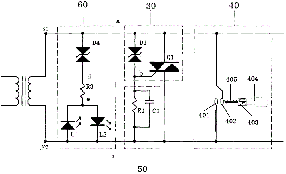
[0042] This embodiment includes an automatic protection circuit 30 and a manual protection mechanism 40 connected in parallel with the secondary side output end of the current transformer for secondary side output circuit open circuit protection. The automatic protection circuit 30 includes a group of basic circuits, which include a two-way voltage regulator diode D1 and a two-way thyristor Q1; the lower end of the two-way voltage regulator diode D1 is connected to the gate G of the two-way thyristor Q1; The MT2 pole of the bidirectional thyristor Q1 is connected to the first terminal K1 of the output terminals, and the MT1 pole of the bidirectional thyristor Q1 is connected to the second terminal K2 of the output terminal.

[0043] A first auxiliary protection circuit 50 is drawn from the connection line b between the bidirectional Zener diode D1 and the gate G of the bidirectional thyristor Q1. The first auxiliary protection circuit 50 includes a resistor R1 and a capacitor C...

Embodiment 2

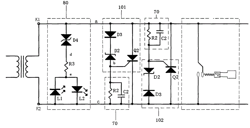
[0050] The only difference between this embodiment and Embodiment 2 is that the automatic protection circuit includes a first basic circuit 101 and a second basic circuit 102 which have the same circuit structure and are reversely connected to the output terminal of the secondary side. Since the circuit structures of the first basic circuit and the second basic circuit are the same, only the first basic circuit is used here as an example for illustration, which includes a zener diode D2 and a rectifier diode D3 connected in series, and the zener diode D2 A silicon-controlled thyristor Q2 connected in parallel with the rectifier diode D3, the silicon-controlled thyristor Q2 is a unidirectional conduction thyristor; wherein the A pole of the Zener diode D2 is connected to the G pole of Q2, and the K pole of the Zener diode D2 is connected to the G pole of the Zener diode D2. The K pole of the rectifier diode D3 is connected, and the A pole of the rectifier diode D3 is connected t...


PUM


Abstract

The invention discloses an open circuit protective circuit for a secondary side output circuit of a current transformer, and belongs to the technical field of overvoltage protection circuits. The open circuit protective circuit for the secondary side output circuit of the current transformer comprises an automatic protective circuit and a manual protective mechanism, wherein the automatic protective circuit and the manual protective mechanism are connected with a secondary side output end of the current transformer in parallel and are used for open circuit protection of the secondary side output circuit. The automatic protective circuit comprises at least one basic circuit, and each basic circuit comprises a thyristor and a voltage stabilizer used for sensing voltages of the two ends of the secondary side output end of the current transformer and controlling the connecting and disconnecting of the thyristor. By the adoption of the open circuit protective circuit for the secondary side output circuit of the current transformer, the situation that high voltage is formed at the open circuit when primary side current of the current transformer is not equal to zero and the open circuit is formed at the output end is avoided, the accidents of arc striking at the open circuit, burning up of contacts, destroyed equipment and the like are further avoided, and production safety and equipment debugging and maintenance convenience are guaranteed. In addition, the manual protective mechanism is arranged, so that two output ends of the current transformer can be in reliable short splice through the manual protective mechanism in the process of equipment debugging and maintenance, and therefore operation safety is guaranteed.

Description

technical field [0001] The invention relates to an overvoltage protection device, in particular to a secondary side protection device of a current transformer. Background technique [0002] In every link of the power system, including power generation, power transformation, power transmission, power distribution and power consumption, it is necessary to measure, protect and control the line (hereinafter referred to as measurement and control). However, the current in the line varies widely, ranging from a few amps to tens of thousands of amps. These currents need to be converted into a relatively uniform current. In addition, the voltage on the line is generally relatively high, such as direct measurement and control. It is very dangerous. The function of the current transformer (CT for short) is to convert the primary current with a large value into a secondary current with a small value through a certain transformation ratio, which is used for protection, measurement and o...

Claims


Application Information

Patent Timeline
Patent Type & Authority Applications(China)
IPC IPC(8): H02H7/00
Inventor 王育松郑映王亚雄
Owner SHENZHEN PUYUAN ELECTRIC TECH
Why Eureka
Try Eureka