On-off operation identification circuit with memory function

A technology for identifying circuits and switching operations, which is applied to the layout of electric lamp circuits, electric light sources, lighting devices, etc., to achieve the effect of long life and simplified operation

Active Publication Date: 2015-04-29
许瑞清
View PDF9 Cites 13 Cited by
  • Summary
  • Abstract
  • Description
  • Claims
  • Application Information

AI Technical Summary

Problems solved by technology

After having the energy required for "memory", consider solving problems at the level of logical operations

Method used


Image

  • On-off operation identification circuit with memory function
  • On-off operation identification circuit with memory function
  • On-off operation identification circuit with memory function

Examples


Embodiment Construction

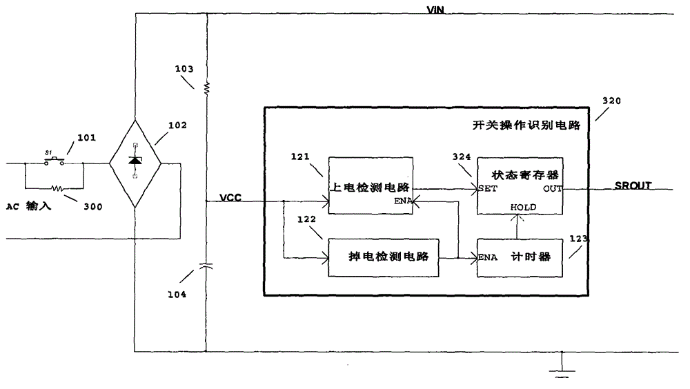
[0037] refer to figure 1 , figure 1 It is a structural schematic diagram of the switch operation identification circuit of the present invention. The circuit judges and recognizes the operation of the control switch 101, and changes its existing state information according to the recognition result, such as state reversal, state clearing, etc. Such as figure 1 As shown, a capacitor 104 is connected between the power supply terminal VCC of the switch operation identification circuit 320 and the reference ground. The 110V or 220V AC provided by the global lighting grid passes through the control switch 101 , is rectified by the rectifier bridge 102 , and then charges the capacitor 104 through the resistor 103 . The voltage VCC on the capacitor 104 provides the power required for the switch operation recognition circuit 320 to work. According to the present invention, a resistor 300 is connected in parallel across the control switch 101 to provide energy for the "memory" func...


PUM


Abstract

The invention discloses an on-off operation identification circuit. According to the basic concept, two ends of a power supply switch are respectively connected with a resistor in parallel, and under the situation that the switch is turned off, the resistor is used for providing weak current (about dozens of microams) for the memory of an LED lamp controller. After the energy for the memory is obtained, the logic operation problem can be considered. The LED switch dimming and color modulation technology with a memory function can be realized by virtue of the lowest cost, no remote controller is needed, the battery polluting the environment is not needed, and no complicated technical means is needed. More human-oriented operation is provided, and the service life of a switch and an LED lamp can be longer.

Description

technical field [0001] The invention relates to the field of light-emitting diode (LED) intelligent lighting, in particular to a switch operation recognition technology with a memory function, and an LED switch dimming circuit and switch coloring circuit based on the recognition technology. Background technique [0002] As a new generation of lighting sources, LEDs are gradually being widely used. Significantly different from other lamps, LED is very suitable for intelligent dimming and color matching, such as switch dimming and switch coloring, wireless remote control dimming and coloring. Intelligent lighting is a major trend in the development of LED lighting. [0003] Switch dimming means that the brightness control of the lamp is realized by turning on and off the LED lamp. For example, a complete three-stage switch dimming process is described as follows: turn on the light for the first time, the LED light is lit at 10W; turn off the light, the light is off; turn on ...

Claims


Application Information

Patent Timeline
Patent Type & Authority Applications(China)
IPC IPC(8): H05B37/02
Inventor 许瑞清刘立国
Owner 许瑞清
Why Eureka
Try Eureka