Cooling system and server system

A server system and cooling system technology, applied in cooling/ventilation/heating transformation, instruments, electrical digital data processing, etc.

Inactive Publication Date: 2015-04-29
DAWNING INFORMATION IND BEIJING
View PDF3 Cites 12 Cited by
  • Summary
  • Abstract
  • Description
  • Claims
  • Application Information

AI Technical Summary

Problems solved by technology

We all know that water with impurities is a good conductor and can cause short circuits in circuit boards
If water is used to cool the cold end of the heat pipe, although the current water-

Method used


Image

  • Cooling system and server system
  • Cooling system and server system
  • Cooling system and server system

Examples


Embodiment Construction

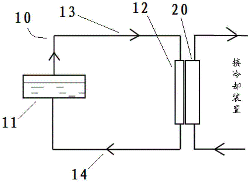
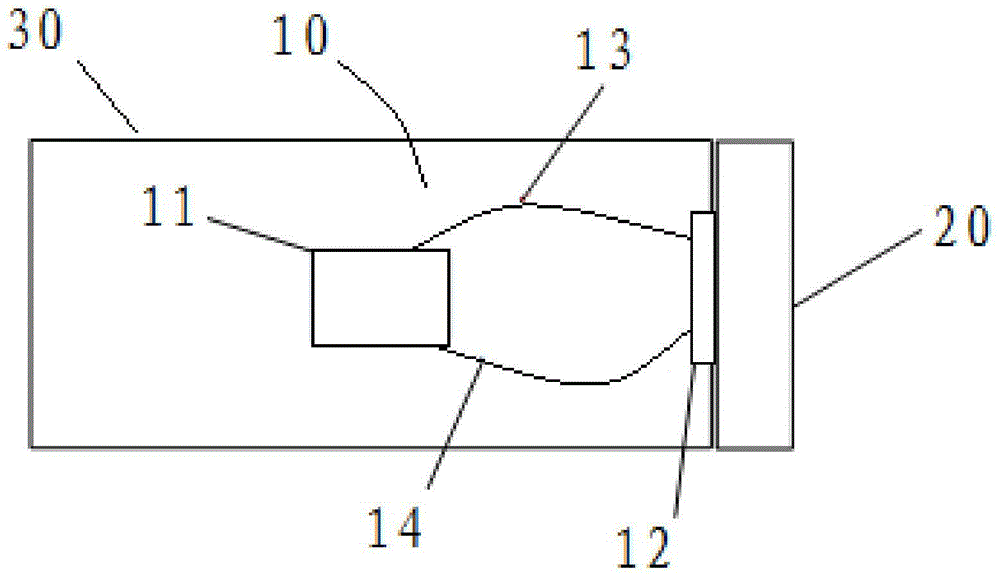
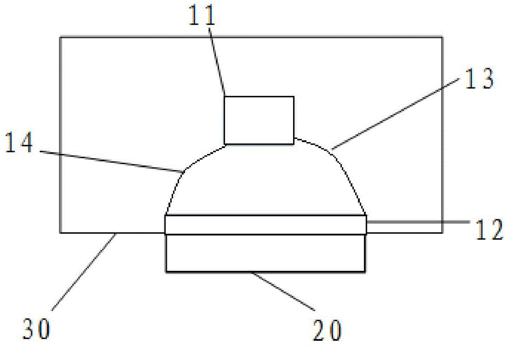
[0022] Now refer to Figure 1 to Figure 3 The cooling system and server system of the present invention will be described.

[0023] In the cooling system of the present invention, it includes a heat pipe 10 and a water cooling plate 20 . Specifically, the heat pipe 10 has a hot end 11, a liquid outlet pipe 13, a cold end 12, and a liquid inlet pipe 14, and the above-mentioned devices are sequentially connected end to end to form a cooling cycle, and the water cooling plate 20 is thermally coupled with the cold end 12 of the heat pipe 10. .

[0024] Specifically, in an optional embodiment, the cold end 12 can be in direct contact with the water cooling plate 20, so as to realize the above-mentioned thermal coupling in the form of direct contact; or, in another optional embodiment, the cold end 12 and the water-cooling plate 20 may be arranged at intervals in the form of heat exchange with each other, so as to realize the above-mentioned thermal coupling in the form of indirec...


PUM


Abstract

The invention provides a cooling system on one hand. The cooling system comprises a heat pipe (10) filled with a refrigerant as well as a water cooling plate (20) which is in thermal coupling with a cold end (12), wherein the heat pipe comprises a hot end (11), a liquid outlet pipe (13), the cold end (12) and a liquid inlet pipe (14) which are communicated end to end to form a cooling circulating loop. The invention provides a server system provided with the cooling system on the other hand. The invention aims to provide the cooling system with a better cooling effect and the server system provided with the cooling system.

Description

technical field [0001] The invention relates to a cooling system and a server system using the cooling system. Background technique [0002] Most of the computers currently in use rely on cold air to cool down the machine, but in data centers, air cooling alone is not enough to meet the heat dissipation requirements of high heat flux density servers. The traditional air-cooling mode adopts the indirect contact cooling method. The heat transfer process is complicated, and there are contact thermal resistance and convective heat transfer thermal resistance. The total thermal resistance is large, and the heat transfer efficiency is low. Larger, requires a lower outdoor low-temperature heat source to guide the heat exchange process. [0003] The heat pipe consists of a shell, a wick and an end cap. The inside of the heat pipe is pumped into a negative pressure state and filled with a suitable liquid, which has a low boiling point and is easy to volatilize. The tube wall has a...

Claims


Application Information

Patent Timeline
IPC IPC(8): H05K7/20G06F1/20
Inventor 沈卫东赵志鸿刘广辉崔新涛童中原张卫平孟祥浩孙振李可
Owner DAWNING INFORMATION IND BEIJING
Why Eureka
Try Eureka