
Adaptive keyhole compression for dynamic contrast-enhanced MRI

An object and space technology, applied in the field of medical imaging, can solve the problems of high temporal resolution, low temporal resolution, and low spatial resolution, and achieve the effect of improving temporal resolution and spatial resolution

Active Publication Date: 2015-04-29
KONINKLJIJKE PHILIPS NV +1
View PDF5 Cites 0 Cited by
  • Summary
  • Abstract
  • Description
  • Claims
  • Application Information

AI Technical Summary

Problems solved by technology

For example, when many lines of k-space are generated to reconstruct each image, each image has high spatial resolution but low temporal resolution
High temporal resolution but low spatial resolution when several lines of k-space are reconstructed into each image

Method used


Image

  • Adaptive keyhole compression for dynamic contrast-enhanced MRI
  • Adaptive keyhole compression for dynamic contrast-enhanced MRI
  • Adaptive keyhole compression for dynamic contrast-enhanced MRI

Examples


Embodiment Construction

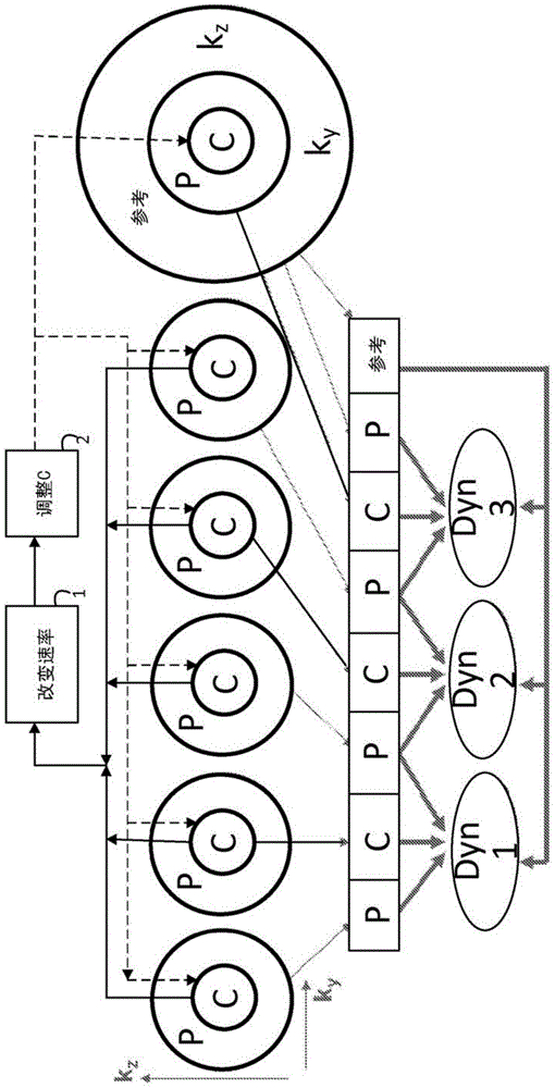
[0022] refer to figure 1 , diagrammatically illustrates an example of reconstruction using adaptive keyhole compression or shared k-space. The K-space is divided into a central part or keyhole and a peripheral part. The division can be further divided into finer delineations. The k-space partitioned geometry can be selected and visualized as concentric geometry, grid format or a combination. The order of sampling can be changed. In the illustrated example, the central portion and half of the peripheral portion are alternately sampled. In the example shown, k-space is divided into three parts: the center, the periphery and the reference or far periphery. The central region C is fully sampled. The sampling of the peripheral portion may include only certain parts of the peripheral k-space, for example alternating halves or less than half. For example, sampling may alternate between near and far peripheral portions of k-space, alternate data lines, sample near portions more ...


PUM


Abstract

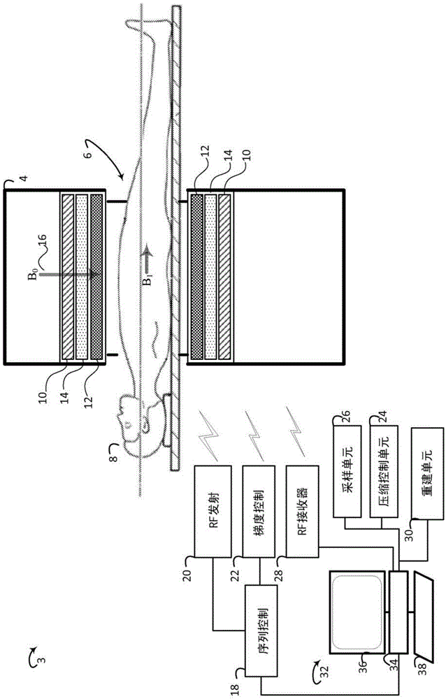
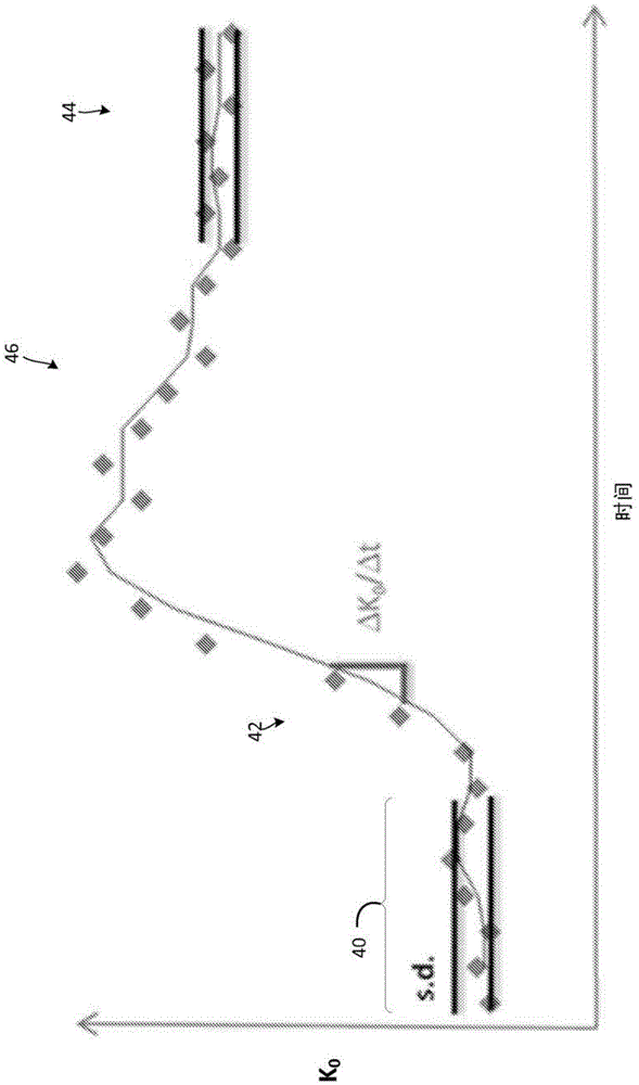
A magnetic resonance imaging system (3) includes a sequence control unit (18), a sampling unit (26), and a control unit (24). The sequence control unit (18) controls a magnetic resonance scanner (4) to acquire compressed magnetic resonance data from an imaged region of a subject. The sampling unit (26) determines a change in a concentration of a contrast agent present in the image region of the subject based on magnetic resonance signals received by a radio frequency receiver. The control unit (24) adjusts a degree of compression of the acquired magnetic resonance data based on the determination made by the sampling unit (26).

Description

technical field [0001] The following generally relates to medical imaging. It finds particular application in connection with magnetic resonance (MR) imaging, MR angiography and dynamic contrast enhanced MR, and will be described with particular reference thereto. However, it should be understood that the present application is also applicable to other uses and is not necessarily limited to the above-mentioned applications. Background technique [0002] Dynamic contrast-enhanced MR imaging images the spread of a contrast agent in a subject's body. A contrast agent for contrast in the MR system is injected into the subject. As the contrast agent moves in the imaging region, images are taken in a sequence showing the movement of the contrast agent in the system of the body over time. Dynamic contrast-enhanced MRI is useful for lesion detection, tumor staging and / or growth, measuring vessel volume and / or leakage, angiography, and the like. Some procedures / protocols are of s...

Claims


Application Information

Patent Timeline
IPC IPC(8): G01R33/48G01R33/56G01R33/561G01R33/563
CPCG01R33/4818G01R33/5601G01R33/5619G01R33/56325G01R33/48G01R33/341G01R33/385G01R33/56316G01R33/5635
Inventor M·K·伊万切维奇T·舍纳韦特
Owner KONINKLJIJKE PHILIPS NV
Learn More