
Implanted-magnet synchronous electric motor

A technology for synchronous motors and magnets, applied to synchronous motors with stationary armatures and rotating magnets, electric components, magnetic circuit rotating parts, etc., can solve the problems of increased usage and increased costs, and achieve the goal of reducing manufacturing costs Effect

Inactive Publication Date: 2015-04-29
MITSUBISHI ELECTRIC CORP
View PDF7 Cites 4 Cited by
  • Summary
  • Abstract
  • Description
  • Claims
  • Application Information

AI Technical Summary

Problems solved by technology

However, in the case of adopting such a structure, the amount of copper, iron, magnets, etc. used as the basic constituent materials of the motor increases, resulting in an increase in cost, so it is not preferable.

Method used


Image

  • Implanted-magnet synchronous electric motor
  • Implanted-magnet synchronous electric motor
  • Implanted-magnet synchronous electric motor

Examples


Embodiment approach

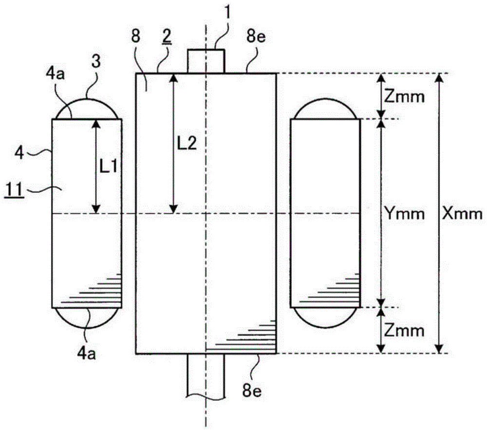
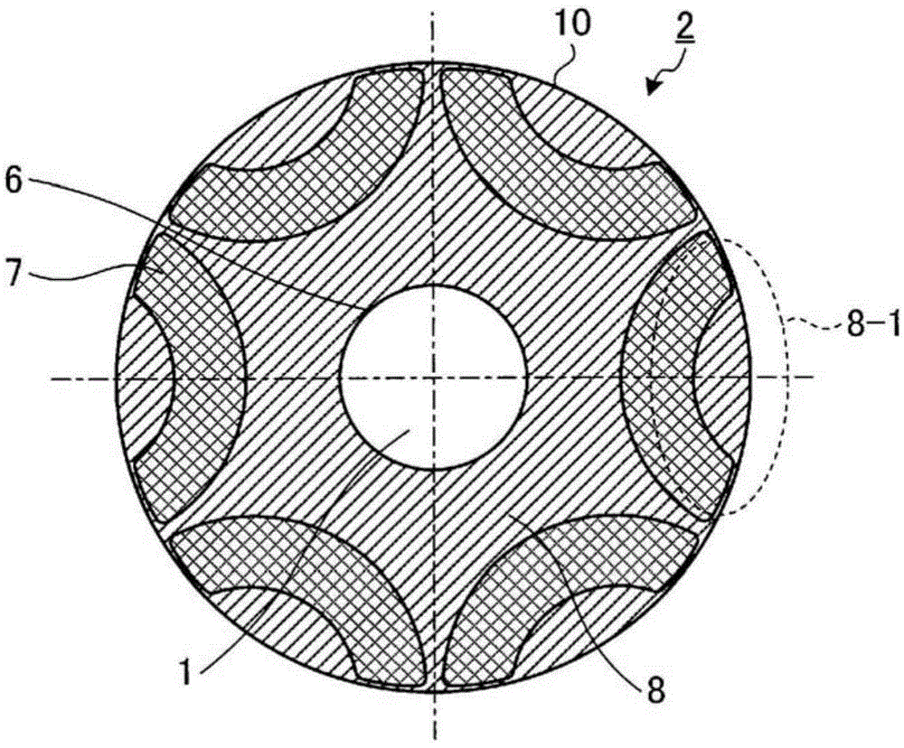
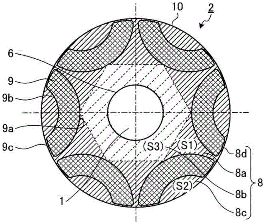
[0051] figure 1 It is a side view of the embedded magnet type synchronous motor according to the embodiment of the present invention, figure 2 yes figure 1 A cross-sectional view of rotor 2 is shown. image 3 yes figure 1 The sectional view of the rotor core 8 shown, Figure 4 It is an enlarged view of the outer peripheral side core part 8-1.

[0052] figure 1 The illustrated embedded magnet synchronous motor has a stator 11 and a rotor 2 . The stator 11 includes a stator core 4 and a winding 3 wound on the stator core 4 as the main structure, wherein the stator core 4 is punched out along the rotation axis by punching a silicon steel plate called a core punching sheet with a die. 1 is formed by stacking multiple sheets in the axial direction. The rotor 2 is rotatably arranged on the inner peripheral side of the stator 11 . The rotor 2 has, as a main structure, a rotating shaft 1 for transmitting rotational energy and a rotor core 8 provided on the outer peripheral po...


PUM


Abstract

In the rotor core 8, three or more magnet housing holes for housing magnets, which are arranged in number corresponding to the number of poles in a circumferential direction of the rotor core and constitute a magnetic pole, are formed in the circumferential direction, and when it is assumed that a stack thickness of the rotor core is X, a stack thickness of the stator core is Y, a sectional area of a core portion surrounded by a line connecting midpoints of an inner diameter side surface of each of the magnet housing holes is S3, a sectional area of an outer-peripheral-side core portion provided between an outer diameter side surface of each of the magnet housing holes and an outer periphery of the rotor core is S2, a sectional area obtained by subtracting the sectional area S2 and the sectional area S3 from a sectional area of the rotor core is S1, and a magnetic force of the magnet is "a", the rotor core is formed so as to satisfy the relation of X>Y and X<Y(1+(S2 / S1) / a×2), with opposite ends thereof overhanging opposite ends of the stator core.

Description

technical field [0001] The present invention relates to an embedded magnet synchronous motor (IPMSM) in which a permanent magnet is embedded in a rotor core. Background technique [0002] In embedded magnet synchronous motors, a general method of achieving higher magnetization is to increase the axial length of the rotor core (rotor lamination thickness) and the axial length of the stator core (stator lamination thickness) together. However, such a configuration is not preferable because the amount of copper, iron, magnets, etc. used as basic constituent materials of the motor increases to increase the cost. In the conventional embedded magnet type synchronous motor represented by the following patent document 1, since the thickness of the rotor lamination is formed larger than the thickness of the stator lamination (overhang), the direct material cost is only the iron and the magnet constituting the rotor. That is, the manufacturing cost can be suppressed. Furthermore, in...

Claims


Application Information

Patent Timeline
Patent Type & Authority Applications(China)
IPC IPC(8): H02K21/14H02K1/27
CPCH02K1/276H02K1/2766H02K21/14H02K2213/03H02K1/06
Inventor 土田和庆及川智明
Owner MITSUBISHI ELECTRIC CORP
Learn More