Annular gap-type centrifugal extractor with vertical mixed baffle

A mixing baffle and annular gap technology, which is applied in the direction of liquid solution solvent extraction, etc., can solve the problem of insufficient mixing of two-phase liquids, and achieve the effects of improving mass transfer efficiency, strengthening mixing intensity, and simple structure

Active Publication Date: 2015-05-06
TSINGHUA UNIV
View PDF3 Cites 7 Cited by
  • Summary
  • Abstract
  • Description
  • Claims
  • Application Information

AI Technical Summary

Problems solved by technology

Recent experimental studies and CFD simulation studies have found that the two-phase liquid mixture in the annulus of the centrifugal extractor has a water-rich phase region in the lower part and an organic-rich...

Method used


Image

  • Annular gap-type centrifugal extractor with vertical mixed baffle
  • Annular gap-type centrifugal extractor with vertical mixed baffle
  • Annular gap-type centrifugal extractor with vertical mixed baffle

Examples


Embodiment 1

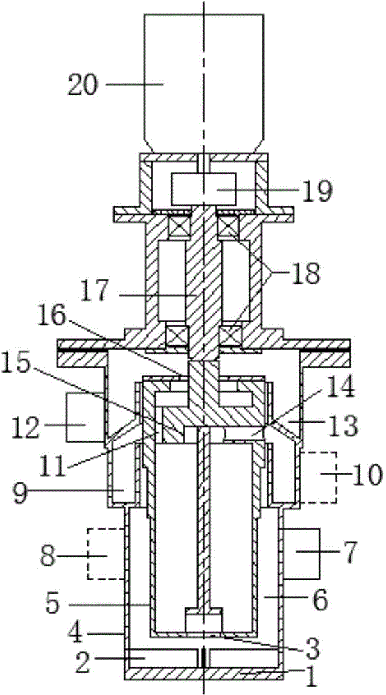
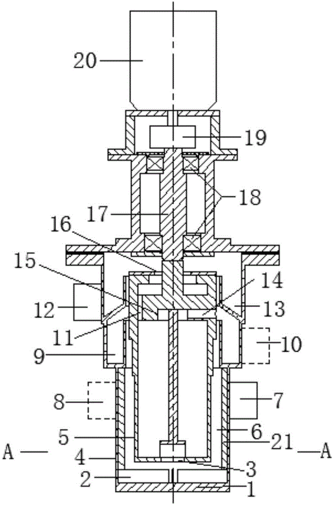
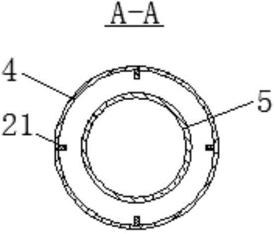
[0019] The existing annular gap centrifugal extractor with a drum diameter of 10 mm is adopted, and the annular gap centrifugal extractor mainly includes a fixed blade 2, a casing 4, a drum 5, a light phase inlet pipe 7, a heavy phase inlet pipe 8, Light phase collecting ring 9, light phase outlet pipe 10, heavy phase vertical channel 11, heavy phase outlet pipe 12, heavy phase collecting ring 13, light phase horizontal channel 14, light phase weir 15, heavy phase weir 16, main shaft 17, bearing 18. The shaft coupling 19 and the motor 20, wherein the inner wall of the lower section of the housing is smooth; the present invention adopts an annular gap type centrifugal extractor with a drum diameter of 10 mm. In addition to the above-mentioned structure, it is manufactured by wire cutting. Four vertical mixing baffles 21 are evenly arranged on the inner wall of the lower section of the shell, and the size in the radial direction is 1 mm, and the size in the circumferential direct...

Embodiment 2

[0021] At present, an annular gap type centrifugal extractor with a drum diameter of 70 mm mainly includes fixed blades 2, a casing 4, a drum 5, a light phase inlet pipe 7, a heavy phase inlet pipe 8, a light phase collection ring 9, a light phase Outlet pipe 10, heavy phase vertical channel 11, heavy phase outlet pipe 12, heavy phase collecting ring 13, light phase horizontal channel 14, light phase weir 15, heavy phase weir 16, main shaft 17, bearing 18, coupling 19 and motor 20, wherein the inner wall of the lower section of the shell is smooth; the new annular gap centrifugal extractor with a drum diameter of 70mm includes the above-mentioned structure, and is evenly distributed on the inner wall of the lower section of the shell 4 by means of welding. A vertical mixing baffle 21, the dimension in the radial direction is 4mm, the dimension in the circumferential direction is 2mm (that is, the radial thickness is 4mm, and the circumferential width is 2mm), and the height is ...


PUM

PropertyMeasurementUnit
Sizeaaaaaaaaaa
Sizeaaaaaaaaaa
Diameteraaaaaaaaaa

Abstract

The invention discloses an annular gap-type centrifugal extractor with a vertical mixed baffle and belongs to the field of chemical machinery equipment. On the basis of existing annular gap-type centrifugal extractor structure, the annular gap-type centrifugal extractor is characterized in that at least two vertical mixed baffles are uniformly arranged on the inner wall of the lower section of the shell, wherein the lower ends of the vertical mixed baffles are connected with bottom of the shell while the upper ends are connected with the lower part of a light phase colleting ring. According to the invention, the bigger the drum diameter is, the larger the sizes and amounts of the vertical mixed baffles are. According to the invention, the mixing strength of two-phase liquids in the annular gap is strengthened to effectively improve mass transfer efficiency. The annular gap-type centrifugal extractor is characterized by being simple in structure, low in cost, easy in processing and manufacturing and wide in application range. The application level of existing annular gap-type centrifugal extractors is greatly increased, so as to promote the application of the annular gap-type centrifugal extractors in various industrial fields.

Description

technical field [0001] The invention relates to an annular gap type centrifugal extractor, which belongs to the field of chemical machinery equipment. Background technique [0002] The annular gap centrifugal extractor relies on strong centrifugal force to realize the phase separation of the two-phase mixed liquid. Metallurgy and nuclear chemical industry and other fields. [0003] The existing annular gap centrifugal extractor mainly includes fixed blade 2, shell 4, drum 5, light phase inlet pipe 7, heavy phase inlet pipe 8, light phase collection ring 9, light phase outlet pipe 10, heavy phase vertical Channel 11, heavy phase outlet pipe 12, heavy phase collecting ring 13, light phase horizontal channel 14, light phase weir 15, heavy phase weir 16, main shaft 17, bearing 18, coupling 19, motor 20, of which, light phase inlet The pipe 7 and the heavy phase inlet pipe 8 communicate with the inner cavity of the shell 4, the light phase outlet pipe 10 communicates with the l...

Claims


Application Information

Patent Timeline
IPC IPC(8): B01D11/04
Inventor 段五华
Owner TSINGHUA UNIV
Why Eureka
Try Eureka