Oil well thermal cleaning filter

A filtration device and hot washing technology, applied in the fields of filtration and separation, fixed filter element filters, chemical instruments and methods, etc., can solve the problems of high manufacturing and use costs, complex design, difficulty, etc., and achieve easy individual control and device design. Reasonable and easy to promote and use

Inactive Publication Date: 2015-05-06
姬丙兰
View PDF0 Cites 1 Cited by
  • Summary
  • Abstract
  • Description
  • Claims
  • Application Information

AI Technical Summary

Problems solved by technology

[0002] Processed high-pressure water is required in the oilfield oil production and water injection process. Usually, the purification work is carried out at the water injection pump station. However, during the long-distance transportation of the purified water to the oil well head, some new mechanical impurities are usually unavoidable. Therefore, in the It is necessary to filter again before the water injection port of the oil well, otherwise, the pump barrel will be blocked after the oil well is injected, and the oil production equipment will be damaged.
And once impurities enter the pump barrel and cause damage to the equipment, it will be cumbersome and difficult to disassemble the equipment for maintenance and cleaning, which will affect the normal oilfield production
Although there are some water injection filtration equipment, most of them are either complicated in design, high in manufacturing and use costs, or the design is too simple, the effect of filtering impurities is not ideal, or the impurity cleaning design in the filtration equipment is unreasonable, and the work of cleaning the filtration equipment is more complicated.

Method used


Image

  • Oil well thermal cleaning filter

Examples


Embodiment Construction

[0013] In order to make the technical solution of the present invention clearer, the present invention will be further described below with examples in conjunction with the accompanying drawings.

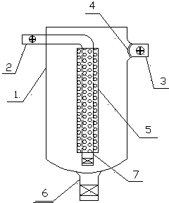
[0014] Depend on figure 1 It can be seen that a kind of oil well hot washing filtering device includes a tank body 1, and the tank body 1 is provided with a water inlet pipe 2, a drain pipe 3 and a sewage discharge pipe 6, and the drain pipe 3 is connected to the oil well hot washing water injection pipe, and the water inlet pipe 2 is connected by the side of the tank body. The upper part of the wall extends horizontally into the center of the inner cavity of the tank and bends toward the bottom of the tank to form a vertical section. The vertical section is provided with a section of water outlet filter element 5 from inside to outside. The bottom of the water outlet filter element 5 is the impurity precipitation section 7 of the water inlet pipe. 1 There are 6 outlets for sewage p...


PUM


Abstract

The invention relates to an oil well thermal cleaning filter. The oil well thermal cleaning filter comprises a tank body, wherein the tank body is provided with a water intake pipe, a water exhaust pipe and a discharge pipe; the water exhaust pipe is connected with an oil well thermal cleaning water intake pipe; the water intake pipe extends horizontally from the upper part of the side wall of the tank body into the center of an inner cavity of the tank body and bends toward the bottom to form a vertical water exhaust filter element from inward to outward; the bottom of the water exhaust filter element is a water intake pipe impurity sedimentation section; the bottom of the tank body is provided with a discharge pipe opening; the upper part of the lateral wall, opposite to the water intake pipe, of the tank body is provided with the water exhaust pipe; the water exhaust pipe opening at the side wall is provided with an arc filter screen protruding towards the inside of the tank body cavity; the bottom of the tank body is provided with an arc bottom surface protruding downward; the arc bottom surface is provided with a discharge pipe opening; a discharge valve is arranged at the discharge pipe opening. According to the water injection filter, the thermal cleaning water intake pipe is directly designed integrally in sections; not only can filtering water injection from inward to outward be realized, but also impurities can be discharged and cleaned by water injection; the detailed design is relatively reasonable; the filtering effect is good; the sewage discharge is simple and complete; the structure is simple; the oil well thermal cleaning filter is easy to popularize.

Description

technical field [0001] The invention relates to the technical field of oil field auxiliary tools, in particular to an oil well hot washing and filtering device. Background technique [0002] Processed high-pressure water is required in the oilfield oil recovery and water injection process. Usually, the purification work is carried out at the water injection pump station. However, during the long-distance transport of the purified water to the oil well head, some new mechanical impurities are usually unavoidable. Therefore, in It is necessary to filter again before the water injection port of the oil well, otherwise it will cause blockage of the pump barrel after the oil well is injected, resulting in damage to the oil production equipment. Moreover, once impurities enter the pump barrel and cause damage to the equipment, it will be cumbersome and difficult to disassemble the equipment for maintenance and cleaning, which will affect normal oilfield production. Although there...

Claims


Application Information

Patent Timeline
Patent Type & Authority Applications(China)
IPC IPC(8): B01D29/56B01D29/94
Inventor 曹岚
Owner 姬丙兰
Why Eureka
Try Eureka