
Ferrite cleaning and baking equipment and realization method thereof

A technology of drying equipment and realization method, applied in the direction of using liquid cleaning method, cleaning method and utensils, drying, etc., can solve the problem of insufficient drying of ferrite products, unclean ferrite products, and downstream processes. Problems such as long process operation time, to achieve the effect of simple structure, low cost and high production efficiency

Inactive Publication Date: 2015-05-06
HENGDIAN GRP DMEGC MAGNETICS CO LTD
View PDF11 Cites 6 Cited by
  • Summary
  • Abstract
  • Description
  • Claims
  • Application Information

AI Technical Summary

Problems solved by technology

[0004] 1. Ferrite products are not clean;
[0005] 2. Insufficient drying of ferrite products;
[0007] 4. Low economic benefits;
[0008] 5. The defect rate of ferrite products is high
[0009] 6. The working time of the next process (defect inspection) is long

Method used

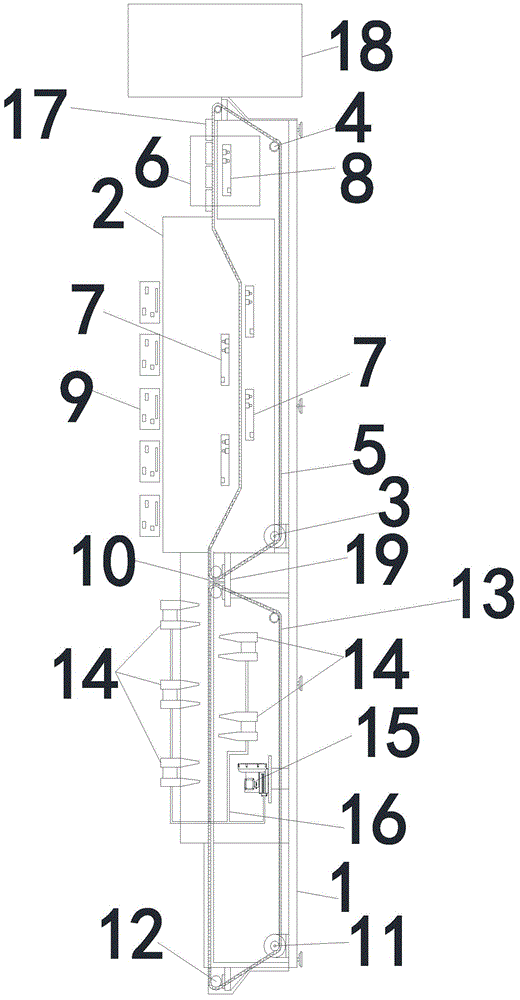

Image

  • Ferrite cleaning and baking equipment and realization method thereof
  • Ferrite cleaning and baking equipment and realization method thereof
  • Ferrite cleaning and baking equipment and realization method thereof

Examples


Embodiment 1

[0045] Such as Figure 1~3As shown, a ferrite cleaning and drying equipment includes an equipment support 1, a first water tank 2 is arranged on the equipment support 1, a first motor 3 is arranged under the first water tank 2, and the first motor 3 passes through several first transition wheels 4 drives the first mesh belt 5 to move. In the present embodiment, there are multiple first transition wheels 4. The inlet end of the first water tank 2 is provided with a second water tank 6. The first mesh belt 5 drives the product 17 to pass through the second water tank 6 and The first water tank 2, the first water tank 2 and the second water tank are independent of each other 6, the first vibrator 7 is set in the first water tank 2, a number of second vibrators 8 are set in the second water tank 6, and the vibrator 9 is connected to the first vibrator 7 And the second vibrator 8, in the present embodiment, there are 5 vibrator 9, which are respectively connected to a vibrator; the...

Embodiment 2

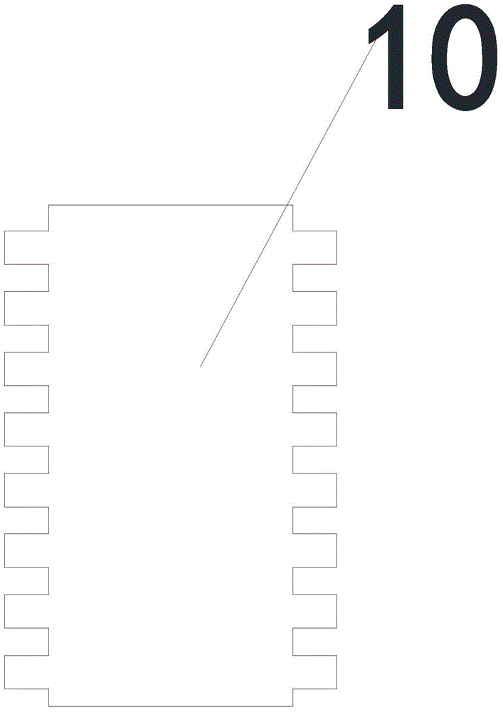
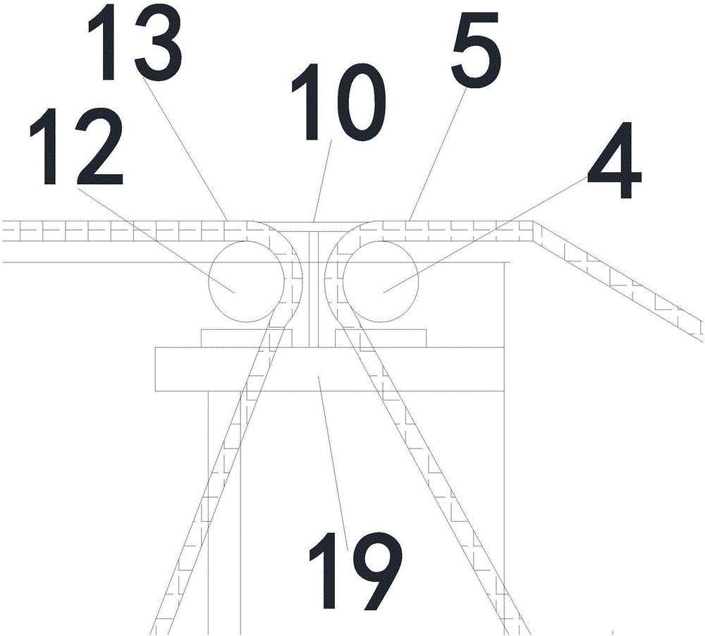
[0061] The difference between the present embodiment and Embodiment 1 is that the distance between the air knife 14 in the present embodiment and the second mesh belt 13 is 65mm, and the distance between the air knife 14 in each group is 200mm. The distance is 800mm; Transition device comprises transition device support 19, and transition device support 19 is located on equipment support 1, and transition device support 19 intermediate positions are provided with roller group (this is the transition plate 10 of this embodiment), and purpose is to make The product 17 in front can be pushed onto the second mesh belt 13 with very little force, and the structure is simple and easy to maintain; the impurity removal rate of rough cleaning is 80%; the impurity removal rate of fine cleaning is 99.5%.

[0062] In this embodiment, both the first water tank 2 and the second water tank 6 are provided with water inlet pipes and water outlet pipes; the water inlet pipes are provided with sol...


PUM


Abstract

The invention discloses ferrite cleaning and baking equipment. The ferrite cleaning and baking equipment comprises an equipment bracket, a first water tank, a first motor, first transitional wheels, a first mesh belt and a second water tank, wherein the first water tank and the second water tank are independent from each other, first vibrators are arranged in the first water tank, a plurality of second vibrators are arranged in the second water tank, vibration exciters are connected with the first and second vibrators, a transitional device is arranged at an outlet end of the first mesh belt, a baking device is arranged at an outlet end of the transitional device and comprises a second motor, the second motor is arranged on the equipment bracket and drives a second mesh belt to move through a plurality of second transitional wheels, the second mesh belt is provided with a plurality of air knives, and the air knives are connected with a hot-air blower through hot-air pipelines. The invention further discloses a realization method of the ferrite cleaning and baking equipment. The ferrite cleaning and baking equipment and the realization method thereof have the characteristics of simple structure, low manufacturing cost, cleanness in cleaning, sufficiency in baking, high production efficiency, high product qualified rate, high economic benefit and the like.

Description

technical field [0001] The invention relates to the production technology of magnetic materials, in particular to a ferrite cleaning and drying equipment and its realization method. Background technique [0002] Magnetic materials have magnetically ordered strong magnetic substances, and in a broad sense also include weak magnetic and antiferromagnetic substances that can apply their magnetic properties and magnetic effects. At present, magnetic materials are widely used in various industries. [0003] The entire production process of magnetic materials must go through processes such as pressing, billet making, sintering, grinding, cleaning, drying, surface defect inspection, and boxing. In the prior art, after grinding ferrite products, there are many powder residues , cleaning and drying are more difficult, and there are many disadvantages in the inspection of surface defects in the next process. Therefore the prior art can have the following technical problems: [0004...

Claims


Application Information

Patent Timeline
IPC IPC(8): B08B3/12B08B13/00F26B21/00
CPCB08B3/123B08B13/00F26B21/004
Inventor 牛利博林百煌杜俊杰吕阳军
Owner HENGDIAN GRP DMEGC MAGNETICS CO LTD
Learn More