Adjustable longitudinal reinforcement bracket of variable-helix and continuous-hooped steel reinforcement framework forming machine

A steel frame and variable spiral technology, which is applied in the field of steel frame forming machine stirrup box longitudinal reinforcement support and adjustment device, can solve the problems of sagging deformation, force deviation, affecting the quality of steel frame forming, etc., and achieve simple and effective structure The effect of support

Active Publication Date: 2015-05-06
AUTOMOTIVE ENG CORP
View PDF10 Cites 0 Cited by
  • Summary
  • Abstract
  • Description
  • Claims
  • Application Information

AI Technical Summary

Problems solved by technology

Due to the long longitudinal ribs, the longitudinal ribs at the back of the stirrup box are prone to sagging deformation, and at the same time, the free longitudinal ribs on the rear side will be offset due to the skeleton formation of the front longitudinal ribs, resulting in the stirrups The box cannot work normally, which affects the forming quality of the steel skeleton

Method used


Image

  • Adjustable longitudinal reinforcement bracket of variable-helix and continuous-hooped steel reinforcement framework forming machine
  • Adjustable longitudinal reinforcement bracket of variable-helix and continuous-hooped steel reinforcement framework forming machine
  • Adjustable longitudinal reinforcement bracket of variable-helix and continuous-hooped steel reinforcement framework forming machine

Examples


Embodiment 1

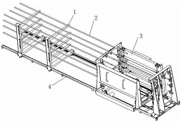
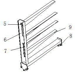
[0022] Example one: such as figure 2 As shown, the bracket is composed of a walking frame 6 on which a walking wheel 8 that cooperates with the steel frame machine track 4 to form a moving pair and four forks 9 for supporting the longitudinal ribs 2 are provided. The walking frame 6 is L-shaped, the vertical side of the walking frame 6 is connected with the fork 9 and the two ends of the horizontal side are connected with the walking wheel 8. The fork 9 is of a variable cross-section type, and the cross-sectional size decreases from the end of the near traveling frame to the end of the remote traveling frame. Two slides 7 are also provided on the walking frame 6. According to the arrangement requirements of the longitudinal ribs 2, the position of the fork 9 on the slide 7 is adjusted, and the fork 9 is fixed on the walking frame 6 with bolts 5. The upper surface of the fork 9 in contact with the longitudinal rib 2 is parallel to the horizontal side of the walking frame 6.

Embodiment 2

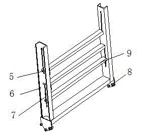
[0023] Embodiment two: such as image 3 As shown, the bracket 1 is composed of a walking frame 6 on which a walking wheel 8 that cooperates with the steel frame machine track 4 to form a moving pair and three forks 9 for supporting the longitudinal ribs 2 are provided. The walking frame 6 is U-shaped, the two symmetrical vertical sides of the walking frame 6 are connected to the two ends of the fork 9 respectively, and the two ends of the horizontal side are connected to the walking wheels 8. The fork 9 is of equal section type. A slideway 7 is provided on the walking frame 6, and the position of the fork 9 on the slideway 7 is adjusted and fixed on the walking frame 6 by bolts 5. The upper surface of the fork 9 in contact with the longitudinal rib 2 is parallel to the horizontal side of the walking frame 6.

[0024] After the bracket 1 is arranged on the steel frame machine track 4, arrange the longitudinal ribs 2 as required, and then adjust the fork 9 on the bracket 1 so tha...


PUM


Abstract

The invention discloses an adjustable longitudinal reinforcement bracket of a variable-helix and continuous-hooped steel reinforcement framework forming machine. The bracket is mounted on a rail of the steel reinforcement framework forming machine and consists of a walking frame, and walking wheels, which are matched with the rail of the steel reinforcement framework forming machine so as to form moving pairs, and a plurality of supporting forks which are used for supporting longitudinal reinforcements are arranged on the walking frame; the walking frame is L-shaped or U-shaped, the vertical edge of the walking frame is connected with the supporting forks, and the two ends of the horizontal edge are connected with the walking wheels; the walking frame is further provided with a slideway, and the supporting forks are fixedly arranged on the walking frame through bolts after the positions of the supporting forks on the slideway are adjusted. The bracket is simple in structure, can be used for supporting the longitudinal reinforcements so as to enable the longitudinal reinforcements to keep original straightness, and can also be used for adjusting longitudinal reinforcement arrangement conditions.

Description

Technical field [0001] The invention belongs to the technical field of reinforcement frame forming construction in the construction industry, and particularly relates to a longitudinal reinforcement and adjustment device of a stirrup box of a reinforcement frame forming machine. Background technique [0002] Reinforcement skeleton forming uses a special seam welding machine to weld multiple circular or square longitudinal reinforcements and spiral stirrups wound on the longitudinal reinforcement. When the reinforcement skeleton is formed, a drive system is required to drive the entire longitudinal reinforcement and the formed skeleton The relative traction system rotates to realize the winding of the stirrups on the longitudinal bars. This forming method has improved the mechanization level of the steel skeleton forming to a certain extent, but there is still a gap with the energy-saving and environmentally-friendly production process advocated by the country, and for different sp...

Claims


Application Information

Patent Timeline
Patent Type & Authority Applications(China)
IPC IPC(8): B21F3/02B21F27/20
Inventor 张明勤马荣全姚玉善孟宪举苗冬梅原政军王晴刘昆王凯靳斐郝圣文张旭
Owner AUTOMOTIVE ENG CORP
Why Eureka
Try Eureka