
Metal powder preparation method and device based on DC (Direct Current) resistance heating non-contact smelting

A metal powder, non-contact technology, applied in the field of gas atomization, can solve the problems of unable to stably control the flow rate of molten metal, and cannot meet the needs of industrial production, so as to facilitate real-time measurement and monitoring, reduce heating burden, and improve feeding efficiency Effect

Inactive Publication Date: 2015-05-06
CHINA JIUYUAN HI TECH EQUIP
View PDF7 Cites 15 Cited by
  • Summary
  • Abstract
  • Description
  • Claims
  • Application Information

AI Technical Summary

Problems solved by technology

[0006] Self-suspension smelting technology (for example, the technology disclosed in Wei Jianjun's dissertation "Preparation of Metal and Alloy Nanoparticles and Their Structural Properties by Self-suspension Directed Flow Method") The non-contact state of the molten metal can always be maintained, but the flow rate of the molten metal cannot be stably controlled, so it cannot meet the needs of industrial production

Method used


Image

  • Metal powder preparation method and device based on DC (Direct Current) resistance heating non-contact smelting
  • Metal powder preparation method and device based on DC (Direct Current) resistance heating non-contact smelting

Examples


Embodiment 1

[0052] A method for preparing metal powder based on direct resistance heating non-contact smelting, comprising the following steps:

[0053] Step 1: Make one end of the metal rod pass through the electrified graphite area at a constant speed.

[0054] Step 2: the metal rod is heated and melted in the electrified graphite region.

[0055] Step 3: The molten metal continuously forms metal droplets under the action of gravity.

[0056] Step 4: The metal liquid droplets continuously drop into the gas atomization area.

[0057] Step 5: The high-pressure and high-speed inert gas breaks up the metal droplets in the gas atomization area.

[0058] Step 6: The metal droplets are broken up by the impact and then cooled to form metal powder.

[0059] All the above steps are usually carried out under vacuum conditions, because usually metals can chemically react with certain components in the air, and the components change.

[0060] The above method is suitable for the production of meta...

Embodiment 2

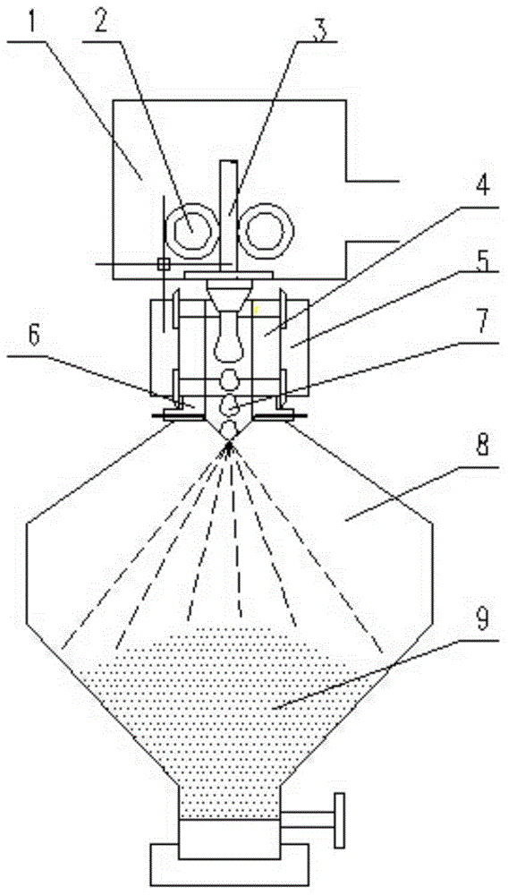
[0064] A metal powder preparation device based on direct resistance heating non-contact smelting, Such as figure 1 shown, including:

[0065] A vacuum chamber 1, the vacuum chamber 1 is provided with an air extraction port and an outlet of the metal rod 3, and the air extraction port is connected to a vacuum extraction device;

[0066] A pair of rollers 2 arranged in the vacuum chamber 1, the axes of the two rollers 2 are parallel, the rotation directions of the two rollers 2 are opposite, and the rotation surface between the two rollers 2 The gap matches the diameter of the metal rod 3; the gap between the rotating surfaces of the two rollers 2 communicates with the outlet of the metal rod 3;

[0067] Both ends are provided with open graphite tubes 4, one end of the graphite tube 4 is connected to the outlet of the metal rod 3, and the other end is connected to the gas atomization nozzle 6 and the powder collector 8 in sequence;

[0068] The exterior of the graphite tube...

Embodiment 3

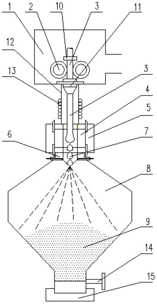
[0075] A metal powder preparation device based on direct resistance heating non-contact melting, such as figure 2 shown, including:

[0076] The vacuum chamber 1 is provided with an air suction port and an outlet of the metal rod 3, and the air suction port is connected with a vacuum suction device.

[0077] The vacuum chamber 1 is provided with a feed guide sleeve 10, a discharge guide sleeve 11 and a pair of rollers 2. The axes of the two rollers 2 are parallel, the rotation directions of the two rollers 2 are opposite, and the rotation surfaces of the two rollers 2 The gap between them matches the diameter of the metal rod 3; the axes of the feed guide sleeve 10, the discharge guide sleeve 11 and the quartz glass tube 12 are collinear; The gap between the material guide sleeve 10, the two rollers 2, the discharge guide sleeve 11 and the outlet of the metal rod 3.

[0078] A quartz glass tube 12 with a coil 13 wound outside, one end of the quartz glass tube 12 is connecte...


PUM


Abstract

The invention relates to a metal powder preparation method and device based on DC (Direct Current) resistance heating non-contact smelting. The metal powder preparation method comprises the following steps: enabling one end of a metal rod to pass through an electrified graphite area at a uniform speed; heating to melt the metal rod in the electrified graphite area; continuously forming metal liquid drops from molten metal under the action of the gravity; continuously dripping the metal liquid drops to a gas atomization area; impinging and scattering the metal liquid drops by high-pressure and high-speed inertial gas in the gas atomization area, and cooling to form metal powder. The metal powder preparation device comprises a vacuum cavity, a pair of idler wheels and a graphite pipe, wherein the two idler wheels are parallel in the axial direction, the rotation directions of the idler wheels are opposite, and a gap between rotating surfaces of the two idler wheels is matched with the diameter of the metal rod; the gap between the rotating surfaces of the two idler wheels is communicated with a metal rod outlet; one end of the graphite pipe is connected with the metal rod outlet, and the other end of the graphite pipe is sequentially connected with a gas atomization nozzle and a powder collector. According to the metal powder preparation method and device, the flow velocity of molten metal liquid can be stably controlled, and the industrial production demands can be met.

Description

Technical field [0001] The present invention involves the field of gas atomization technology. Specifically, it involves a metal powder preparation method and device based on direct resistance heating non -contact melting. Background technique [0002] The powder prepared by the gas atomization technology is small, high in spherical, and low oxygen content. It is currently an important method for producing high -performance spherical metal powder. [0003] The production principle of gas atomization technology is to use high -pressure gases to melt the metal atomicly melted into a small metal powder. [0004] Generally, the gas atomized powder device is melted by melting, that is, the metal is melted in the cricket, and then the melting metal is dumped into the diversion device.Formation of fine powder.It is feasible to prepare low -melting point metal powder, but there are still difficulties in preparation of high melting points and lively metal powder.The main reason is that th...

Claims


Application Information

Patent Timeline
IPC IPC(8): B22F9/08
Inventor 龚伟志赵午云孙伟孙静
Owner CHINA JIUYUAN HI TECH EQUIP
Learn More