Supercharge Your Innovation With Domain-Expert AI Agents!

A rotary machining tool

A rotary machining and tool technology, applied in the field of metal cutting, can solve the problems of dovetail groove wear, reduced tool service life, damage, etc., and achieves good impact resistance, improved impact resistance, and stable and reliable positioning.

Active Publication Date: 2017-02-22
ZHUZHOU CEMENTED CARBIDE CUTTING TOOLS CO LTD
View PDF6 Cites 0 Cited by
  • Summary
  • Abstract
  • Description
  • Claims
  • Application Information

AI Technical Summary

Problems solved by technology

The tool transmits the torque through the action surface of the coupling part in a slit of the sheath body to make the elastic protrusion deviate. In the actual cutting process, there are the following problems: 1. Due to the large radial area of ​​the elastic protrusion, it is difficult to load and unload the cutting tool. In some cases, the dismounting tool bears a large force, and the force-bearing area of ​​the dismounting tool is small, and the dismounting tool and the main body of the sheath are easily damaged by indentation, thereby reducing the service life of the tool, and when loading and unloading the cutting parts, the elastic protrusion If the opening angle that can be achieved is too small, the cutting part will slide along the dovetail groove of the main body of the sheath, and friction between the two will be inevitable. However, the main body of the sheath is generally made of materials with relatively poor wear resistance, and often after several times After loading and unloading, the dovetail groove on the main body of the sheath is severely worn, and the main body of the sheath will not be able to form reliable support for the cutting parts without external force, resulting in failure of the main body of the sheath; 2. The main body of the sheath and the cutting parts are parallel to each other The positioning of the dovetail-shaped structure, when the cutting part is subjected to a force parallel to the dovetail-shaped structure, it is easy to cause the cutting part to fall off; 3. The cutting part and the main body of the sheath are centered through the circular groove in the center of the dovetail-shaped structure. The diameter of the groove is limited by the dovetail structure, and at most it can only be equal to the width of the bottom of the dovetail structure, so the centering effect that this circular groove can achieve is limited

Method used


Image

  • A rotary machining tool
  • A rotary machining tool
  • A rotary machining tool

Examples


Embodiment Construction

[0027] The present invention will be further described in detail below in conjunction with the accompanying drawings and specific embodiments.

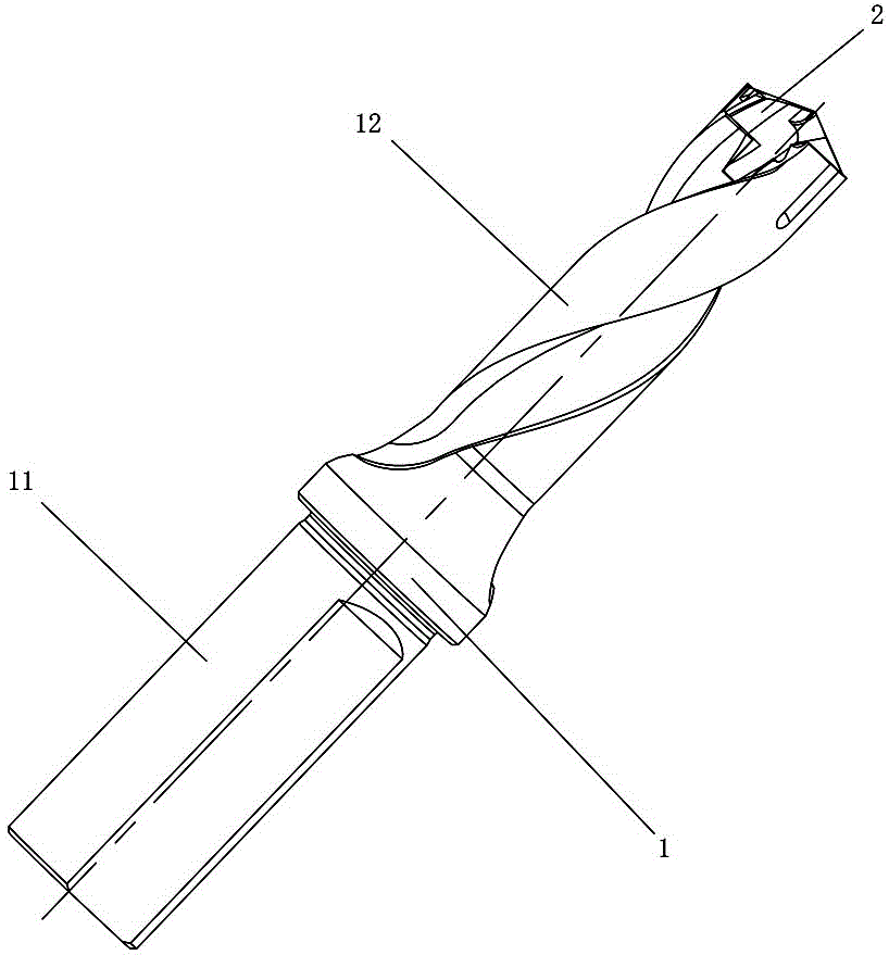
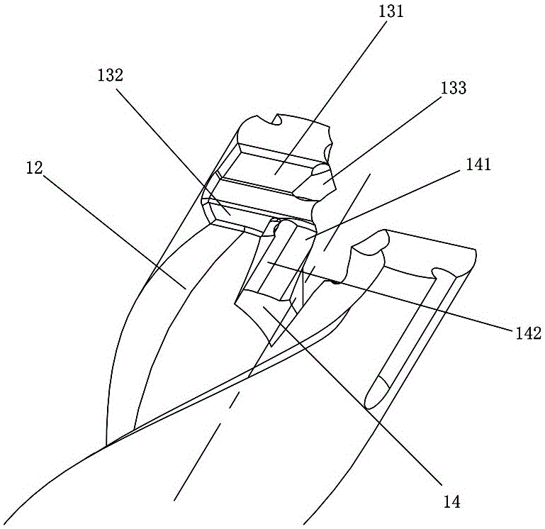
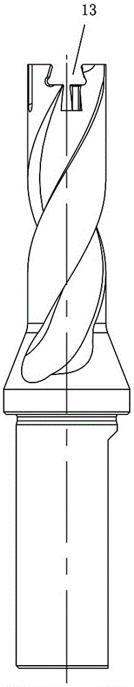
[0028] Figures 1 to 9 An embodiment of the rotary machining tool of the present invention is shown, including a clamping part 1 and a cutting part 2, the clamping part 1 includes a handle 11 and an elastic clamping part 12, and the cutting part 2 is installed on the elastic clamping part 12 Above, the cutting part 2 includes a cutting head 21 and a connecting portion 22. The cutting head 21 is provided with at least two cutting edges 211 and at least two inclined positioning surfaces 212. The inclined positioning surfaces 212 are along the cutting feed direction of the rotary processing tool. The axis of the rotary machining tool is inclined, the transition surface between the cutting head 21 and the connecting portion 22 forms an axial positioning surface 23, the elastic clamping portion 12 is provided with a dovetail groove 13, and...


PUM


Abstract

The invention discloses a rotary machining tool. The rotary machining tool comprises a clamping component and a cutting component, wherein the clamping component comprises a handle part and an elastic clamping part; the cutting part is arranged on the elastic clamping part; the cutting part comprises a cutting head part and a connection part; at least two cutting edges and at least two inclined positioning faces are arranged at the cutting head part; the inclined positioning faces are inclined towards the axis of the rotary machining tool along a cutting feeding direction of the rotary machining tool; an axial positioning face is formed by a transition face between the cutting head part and the connection part; a dovetail groove is formed in the elastic clamping part, and comprises a torque action face for supporting the inclined positioning faces and an axial action face for supporting the axial positioning face; an installation groove is formed in the bottom face of the dovetail groove; the connection part is arranged inside the installation groove. The rotary machining tool provided by the invention has the advantages of simple structure, stability in connection and good anti-impact property.

Description

technical field [0001] The invention relates to the field of metal cutting, in particular to a rotary machining tool. Background technique [0002] In drilling, in order to prolong the service life of the cutting part of the tool, relatively expensive cemented carbide or similar materials are usually used as the tool material. Because such materials have the characteristics of high hardness and good wear resistance, processing is extremely difficult. The material cost and processing cost of the drilling tool are relatively high. At present, the commonly used drilling tools are generally assembled from cutting parts and clamping parts. The cutting parts are made of hard alloys with high hardness and strong wear resistance or similar It is made of high-quality materials, while the clamping parts are made of more elastic materials. When the cutting parts are worn out, the cutting parts can be replaced separately, thereby reducing the cost of materials and processing. [0003] ...

Claims


Application Information

Patent Timeline
Patent Type & Authority Patents(China)
IPC IPC(8): B23B51/00
CPCB23B51/00
Inventor 辛晓伟刘敏刘伟
Owner ZHUZHOU CEMENTED CARBIDE CUTTING TOOLS CO LTD
Features
  • R&D
  • Intellectual Property
  • Life Sciences
  • Materials
  • Tech Scout
  • Unparalleled Data Quality
  • Higher Quality Content
  • 60% Fewer Hallucinations
Learn More