Laser machining fume environment-friendly treatment device and treatment method
A technology of environmental protection treatment and laser processing, which is applied in the direction of combination device, separation method, laser welding equipment, etc., can solve the problems of polluting the environment and damaging the physical and mental health of surrounding residents, etc.
- Summary
- Abstract
- Description
- Claims
- Application Information
AI Technical Summary
Problems solved by technology
Method used
Image

Examples
Embodiment Construction
[0021] In order to make the purpose, technical solution and advantages of the present invention clearer, the technical solution of the present invention will be further described in detail below in conjunction with the accompanying drawings and embodiments. It should be understood that the specific embodiments described here are only used to explain the present invention, not to limit the present invention.
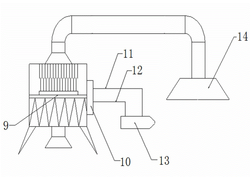
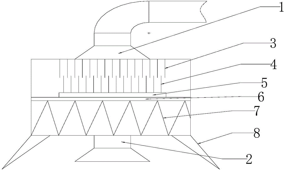
[0022] Laser processing smoke and dust environmental protection treatment device, such as figure 1 As shown, it includes a dust collection module 14 and a dust processor 9, and the dust collection module 14 is connected to the air intake pipe 1 of the dust processor 9 through a delivery pipe. The dust generated by the operation of the laser generator 13 is collected by the dust collection module 4 and then input to the dust processor 9 for processing, and then discharged without pollution. An exhaust fan is installed at the air intake pipe 1 of the soot processor 9, and ...
PUM
 Abstract
Description
Claims
Application Information
 - R&D
- Intellectual Property
- Life Sciences
- Materials
- Tech Scout
- Unparalleled Data Quality
- Higher Quality Content
- 60% Fewer Hallucinations
Browse by: Latest US Patents, China's latest patents, Technical Efficacy Thesaurus, Application Domain, Technology Topic, Popular Technical Reports.
© 2025 PatSnap. All rights reserved.Legal|Privacy policy|Modern Slavery Act Transparency Statement|Sitemap|About US| Contact US: help@patsnap.com