Hydraulic reciprocating compression air pump with quantified and variable pressurization functions

A reciprocating, compressed gas technology, applied in the direction of liquid variable displacement machinery, pumps, multi-stage pumps, etc., can solve problems such as high-pressure chamber and high-pressure piston are prone to heat, cannot work continuously and quickly for a long time, and the structure of the high-pressure air pump is complicated. , to achieve the effect of light weight, simple structure and low maintenance cost

Inactive Publication Date: 2015-05-06
天津市海雅实业有限公司
View PDF8 Cites 8 Cited by
  • Summary
  • Abstract
  • Description
  • Claims
  • Application Information

AI Technical Summary

Problems solved by technology

[0002] The high-pressure air pumps currently on the market generally output high-pressure gas after multi-stage pressurization. This type of high-pressure air pump has a complex structure, low output pressure, and poor heat dissipation. The time works continuously and quickly, and the boosting speed is slow, and the work efficiency is low

Method used


Image

  • Hydraulic reciprocating compression air pump with quantified and variable pressurization functions
  • Hydraulic reciprocating compression air pump with quantified and variable pressurization functions
  • Hydraulic reciprocating compression air pump with quantified and variable pressurization functions

Examples


Embodiment Construction

[0024] The hydraulic reciprocating compressed air pump with quantitative and variable pressure boosting functions of the present invention will be further described below in conjunction with the accompanying drawings and specific embodiments. In the accompanying drawings, the same components as those in the prior art use the same symbols. The following examples are only used to illustrate the present invention but not to limit the present invention.

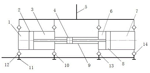
[0025] figure 1 It is a structural schematic diagram of the hydraulic reciprocating compressed air pump of the first embodiment of the present invention. Such as figure 1 As shown, the hydraulic reciprocating compressed air pump with variable boosting function of the first embodiment includes a power reciprocating cylinder 9 in the middle and a left compression cylinder and a right compression cylinder connected to both ends of the power reciprocating cylinder 9 . The two ends of the power reciprocating cylinder piston 4 in the...


PUM


Abstract

A hydraulic reciprocating air pump with the quantified and variable pressurization functions comprises a middle power reciprocating cylinder, a left compression cylinder and a right compression cylinder. The left compression cylinder and the right compression cylinder are connected to the two ends of the power reciprocating cylinder. A piston of the left compression cylinder divides the left compression cylinder into a first working cavity and a second working cavity. A piston of the right compression cylinder divides the right compression cylinder into a third working cavity and a fourth working cavity. The cylinder diameter of the left compression cylinder is equal to the cylinder diameter of the right compression cylinder in the variable pressurization function. Air inlet valves of the first, second, third and fourth working cavities are each provided with a manual ejector rod. Exhaust valves of the four working cavities are connected in parallel and connected with an air outlet. Suction valves are connected in parallel and connected with an air inlet. The cylinder diameter of the left compression cylinder is not equal to the cylinder diameter of the right compression cylinder in the quantified pressurization function, the exhaust valves of the four working cavities and the suction valves are connected in series in different modes to obtain two pressurization effects, and parallel connection two-level pressurization and series connection three-level pressurization are achieved. According to the hydraulic reciprocating air pump, the cylinder diameters of the left and right compression cylinders are changed, and the series and parallel connection loops of the suction valves and the air inlet valves are changed, so that high pressure or super-high pressure of the gas compression pump is easy to achieve.

Description

technical field [0001] The invention relates to a compressed air pump, in particular to a hydraulic reciprocating compressed air pump with quantitative and variable boosting functions. Background technique [0002] The high-pressure air pumps currently on the market generally output high-pressure gas after multi-stage pressurization. This type of high-pressure air pump has a complex structure, low output pressure, and poor heat dissipation. The time works continuously and quickly, and the boosting speed is slow, and the working efficiency is low. Contents of the invention [0003] In order to solve the above-mentioned problems in the prior art, the present invention provides a hydraulic reciprocating compressed air pump with quantitative and variable boosting functions. [0004] The technical scheme that the present invention takes for solving this problem is: [0005] The hydraulic reciprocating compressed air pump with quantitative and variable boosting functions of th...

Claims


Application Information

Patent Timeline
Patent Type & Authority Applications(China)
IPC IPC(8): F04B27/12
Inventor 刘莹韩蕙冰刘怡宁
Owner 天津市海雅实业有限公司
Why Eureka
Try Eureka