
Vibrating material level switch and its vibrating device

A technology of vibration device and material level switch, which is applied to measuring devices, lubrication indicating devices, engine components, etc., can solve the problems of changes in vibration characteristics, affecting vibration characteristics, and lack of penetration, so as to avoid changes in mechanical properties and avoid vibration. Changes in characteristics, effects of ensuring reliability

Active Publication Date: 2017-08-11
深圳计为自动化技术有限公司
View PDF5 Cites 0 Cited by
  • Summary
  • Abstract
  • Description
  • Claims
  • Application Information

AI Technical Summary

Problems solved by technology

[0007] 1. In the existing double-tube vibration structure, the clamping bolts are welded on the diaphragm. This method requires vertical installation and welding. The processing is difficult, the process is complicated, and it is prone to lack of penetration, which will affect the vibration characteristics. Thus affecting the reliability and life of the vibration device
[0008] 2. Since welding will cause changes in the metallographic structure and structure of the diaphragm material, the change in the metallographic structure and structure will lead to changes in the mechanical properties of the material, resulting in changes in vibration characteristics, which will affect the reliability of the vibration device Sexuality, which eventually leads to the life of the vibrating device being affected

Method used


Image

  • Vibrating material level switch and its vibrating device
  • Vibrating material level switch and its vibrating device
  • Vibrating material level switch and its vibrating device

Examples


Embodiment

[0055] This embodiment provides a vibrating material level switch.

[0056] The vibration type material level switch includes a control circuit and a vibration device.

[0057] The control circuit adopts the existing control circuit, and this technology is already very mature, so it is not shown in the drawings of this application, and it is not explained in detail at the same time.

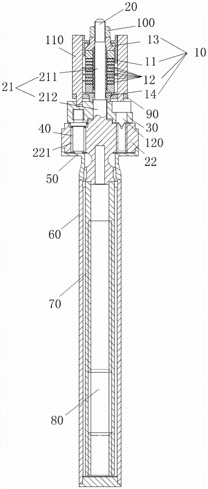
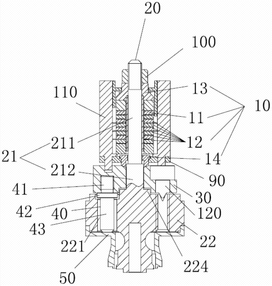
[0058] Please continue to refer figure 1 and 2 , the vibrating device includes a piezoelectric assembly 10 , a tension rod 20 , a bridging block 30 , a pressing piece 40 , a diaphragm 50 , a vibrating outer tube 60 and a vibrating inner tube 70 .

[0059] Please refer to Figure 2-4 , the tension rod 20 includes a rod-shaped mounting body 21 and a transition body 22 whose radial dimension is larger than that of the mounting body 21 . The transition body 22 can be a disc-like structure, the installation body 21 is located above the transition body 22, and the two are of an integrated structure...


PUM


Abstract

The application discloses a vibrating material level switch and a vibrating device thereof. The vibrating device includes a piezoelectric component, a tension rod, a bridging block, a pressing piece, a diaphragm, a vibrating outer tube and a vibrating inner tube. The tension rod includes an installation body and a transition body, and the installation body and the transition body are of an integrated structure with good rigidity and firm structure, which can ensure the vibration transmission between the tension rod and the bridging block. The piezoelectric component and the bridging block are sleeved on the installation body, and the bridging block is located above the transition body, and is pressed and positioned by the pressing bolt, and there is a through hole on the transition body, and the upper part of the pressing part is fixed on the bridging block. The lower part passes through the through hole, and transmits vibration against the diaphragm. The pressing part compresses the diaphragm through the pre-tightening force, and is not welded on the diaphragm. This method will not cause changes in the metallographic structure and structure of the diaphragm material, so it can avoid the metallographic structure and structural changes affecting the reliability of the vibration device. Sex, so as to avoid the life of the vibrating device from being affected.

Description

technical field [0001] The present application relates to a vibrating material level switch, in particular to a vibrating device in the vibrating material level switch. Background technique [0002] In modern industrial and agricultural production, it is often necessary to control the storage of plastic granules, coal powder, grains, flour and other granular or powdery solids, and it is often necessary to detect their accurate positions. [0003] The vibration level switch is a high sensitivity vibration level switch composed of a piezoelectric element and a mechanical resonance structure. The voltage signal is output by the control circuit, which excites the piezoelectric element to drive the matching mechanical element to generate resonance, and transmits it to the detection probe. When the material to be tested is covered by the vibrating detection probe, the vibration amplitude is drastically reduced due to the damping effect of the material. Through the detection recei...

Claims


Application Information

Patent Timeline
Patent Type & Authority Patents(China)
IPC IPC(8): G01F23/00
Inventor 黄河振盛井德陈之聪林强增
Owner 深圳计为自动化技术有限公司
Learn More