Weak current detecting device and method

A detection device and detection method technology, applied in the direction of measurement using digital measurement technology, can solve the problems of low reliability, slow response time, large volume, etc., to avoid thermal noise of resistance, save software control, and wide input range Effect

Inactive Publication Date: 2015-05-06
FOCUSED PHOTONICS
View PDF16 Cites 5 Cited by
  • Summary
  • Abstract
  • Description
  • Claims
  • Application Information

AI Technical Summary

Problems solved by technology

[0009] There are many components required, and the voltage range needs to be judged by software to switch the range. The structure is complex, the volume is large, the accuracy is poor, the reliability is low, and the response time is slow;

Method used


Image

  • Weak current detecting device and method
  • Weak current detecting device and method
  • Weak current detecting device and method

Examples


Embodiment

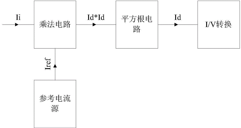
[0034] image 3 Schematically shows the structure diagram of the weak current detection device of the embodiment of the present invention, as image 3 As shown, the weak current detection device includes:

[0035] a reference current source, the reference current source is electrically connected to the first input terminal of the multiplication circuit;

[0036] A multiplication circuit, the second input terminal of the multiplication circuit is connected to the current to be measured;

[0037] A square root circuit, the input end of the square root circuit is electrically connected to the output end of the multiplication circuit;

[0038] An I / V conversion circuit, the input end of the I / V conversion circuit is electrically connected to the output end of the square root circuit.

[0039] In the weak current detection method of the embodiment of the present invention, the weak current detection method includes the following steps:

[0040] (A1) The current Ii to be measure...


PUM


Abstract

The invention provides a weak current detecting device and method. The weak current detecting device comprises a reference power source, a multiplying circuit, a square-rooting circuit and an I/V conversion circuit. The reference power source is electrically connected with the first input end of the multiplying circuit; the second input end of the multiflying circuit is connected with current to be detected; the input end of the square-rooting circuit is electrically connected with the output end of the multiplying circuit; the input end of the I/V conversion circuit is electrically connected with the output end of the square-rooting circuit. The weak current detecting device has the advantage of being wide in dynamic range and the like.

Description

technical field [0001] The invention relates to current detection, in particular to a weak current detection device and method. Background technique [0002] In the application of various sensors, it is often encountered that the output is a weak current signal, and the current signal is usually converted into a voltage signal for detection. The conventional method is to amplify through the operation amplifier with high resistance and low bias current ,Such as figure 1 shown. This approach has many disadvantages: [0003] The dynamic range of detection and the lower limit of the signal are limited by the resistance of the resistor. In order to obtain a wide dynamic range, a resistor with a large resistance must be used, and a large resistance will inevitably bring large thermal noise, which brings a lot to the detection limit of the signal. It is a big trouble. In addition, the resistance of large resistance also brings great difficulties to the selection of the filter ca...

Claims


Application Information

Patent Timeline
Patent Type & Authority Applications(China)
IPC IPC(8): G01R19/25
Inventor 许成鑫刘伟宁张建韩双来
Owner FOCUSED PHOTONICS
Why Eureka
Try Eureka