Three-dimensional reflecting measurement device and method

A measuring device and reflective technology, applied in the direction of measuring device, optical device, radio wave measuring system, etc., can solve the problems of too large or too small measuring angle, unsuitable for the object to be measured, unable to measure, etc., so as to improve the installation efficiency , Improve the efficiency of installation, the effect of light overall weight

Inactive Publication Date: 2015-05-06
SHANGHAI CONSTRUCTION GROUP +3
View PDF8 Cites 0 Cited by
  • Summary
  • Abstract
  • Description
  • Claims
  • Application Information

AI Technical Summary

Problems solved by technology

[0005] The object of the present invention is to provide a three-dimensional reflective measurement device and method, which can be quickly and conveniently pasted on the object to be measured, and can select a suitable reflective surface for measurement at any position, so as to solve the problems caused by the measurement angle being too large or too small and the It is suitable to install reflective prisms on the measured object but cannot be measured, so as to realize fast and accurate measurement in narrow and long areas

Method used


Image

  • Three-dimensional reflecting measurement device and method
  • Three-dimensional reflecting measurement device and method
  • Three-dimensional reflecting measurement device and method

Examples


Embodiment Construction

[0028] The three-dimensional reflective measuring device proposed by the present invention will be described in further detail below in conjunction with the accompanying drawings and specific embodiments. Advantages and features of the present invention will be apparent from the following description and claims. It should be noted that all the drawings are in a very simplified form and use imprecise scales, and are only used to facilitate and clearly assist the purpose of illustrating the embodiments of the present invention.

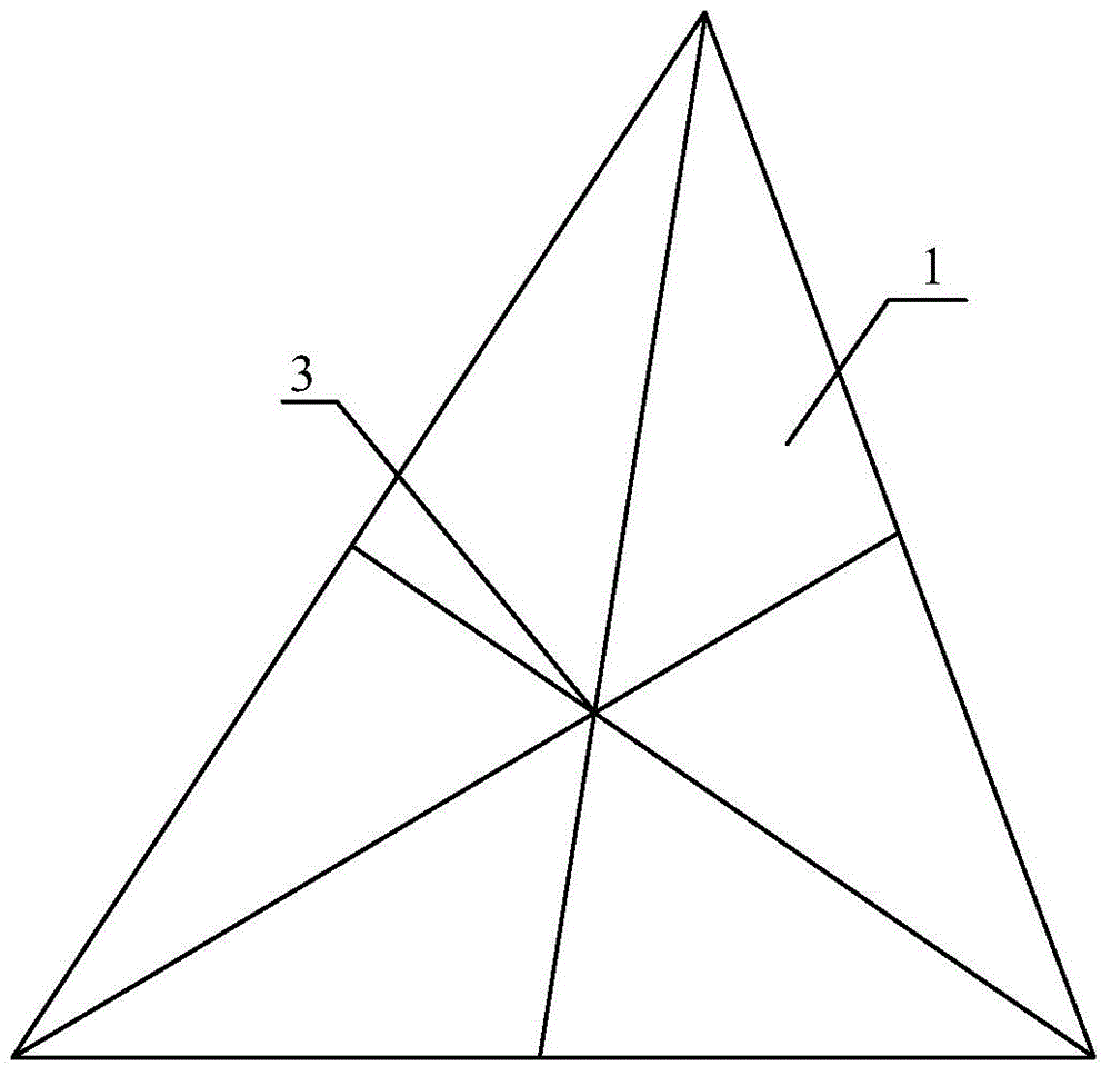
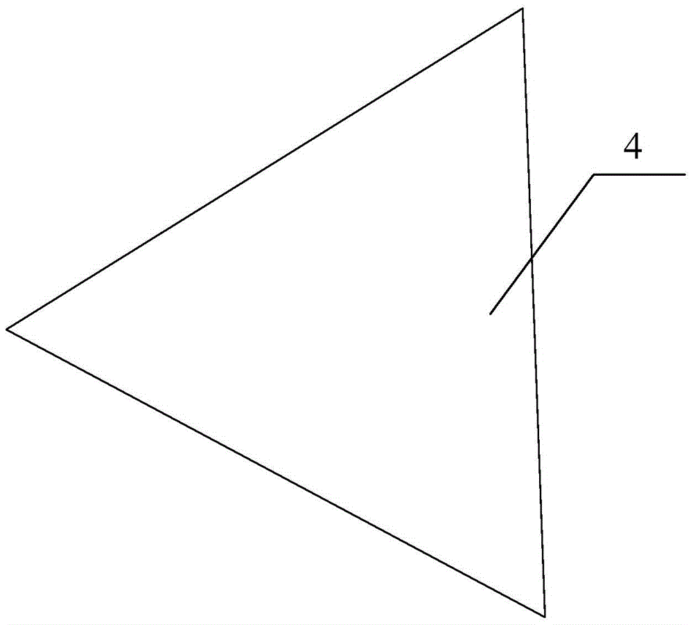
[0029] combine Figure 1 to Figure 4 , the present embodiment discloses a three-dimensional reflective measuring device, comprising a regular pyramid 2 (also referred to as a base material), the bottom surface of the regular pyramid 2 is provided with a bonding layer, and the remaining surfaces are respectively provided with The reflective material layer 3 forms a reflective surface, and the center 3 of each reflective surface is marked on each reflect...


PUM


Abstract

The invention discloses a three-dimensional reflecting measurement device and method. The device comprises a regular pyramid; an adhering layer is arranged on the bottom surface of the regular pyramid, and reflecting material layers are arranged on the rest surfaces of the regular pyramid to form reflecting surfaces; reflecting surface centers are marked on each reflecting surface; a protecting film is arranged on the adhering layer. The method comprises the steps of tearing the protecting film on the bottom surface of the regular pyramid; adhering the regular pyramid on the tested object through the adhering layer; selecting the reflecting surface with a proper measurement angle according to the position relation of a total station and the regular pyramid; aligning to the reflecting surface center; emitting laser to the reflecting surface center, and receiving the laser reflected by the reflecting surface, so as to measure three-dimensional coordinates of the reflecting surface center. With the adoption of the method, the proper reflecting surface can be selected from any position for measuring, thus the problem that excessively large or excessively small measuring angle is unsuitable for mounting a prism and leads to failure of measurement can be solved, a narrow zone can be quickly and accurately measured, and the regular pyramid can be directly, quickly and conveniently adhered to the tested object without mounting and debugging.

Description

technical field [0001] The invention relates to the field of building construction measurement, in particular to a three-dimensional reflective measurement device and method for determining the deformation of the measured object by measuring the change of the three-dimensional coordinates of the measured object. Background technique [0002] At present, there are generally three measurement modes for three-dimensional coordinate measurement: non-reflective measurement, reflective sheet measurement and reflective prism measurement. Among them, the non-reflection measurement mode means that the total station directly aims at the characteristic position of the measured object (i.e. the target), emits laser light, receives the reflected laser light of the target, records the laser running time and the readings of the horizontal dial and vertical dial of the total station, according to Calculate the three-dimensional coordinates of the measured object based on the relative positi...

Claims


Application Information

Patent Timeline
Patent Type & Authority Applications(China)
IPC IPC(8): G01S17/06G01B11/16
CPCG01S17/06G01B11/16
Inventor 黎奎奎吴玲怡陆春王伟良邢俊杨申贤严佳庆季立群何冈陆健航
Owner SHANGHAI CONSTRUCTION GROUP
Why Eureka
Try Eureka