

APPARATUS CONTROL SERVER, APPARATUS CONTROL METHOD, APPARATUS CONTROL SYSTEM, NOTIFICATION APPARATUS, and ROBOT TERMINAL
A device control and server technology, applied in general control systems, control/regulation systems, robots, etc., can solve problems such as impairing user convenience
- Summary
- Abstract
- Description
- Claims
- Application Information
AI Technical Summary
Problems solved by technology
Method used
Image

Examples
Embodiment approach 1
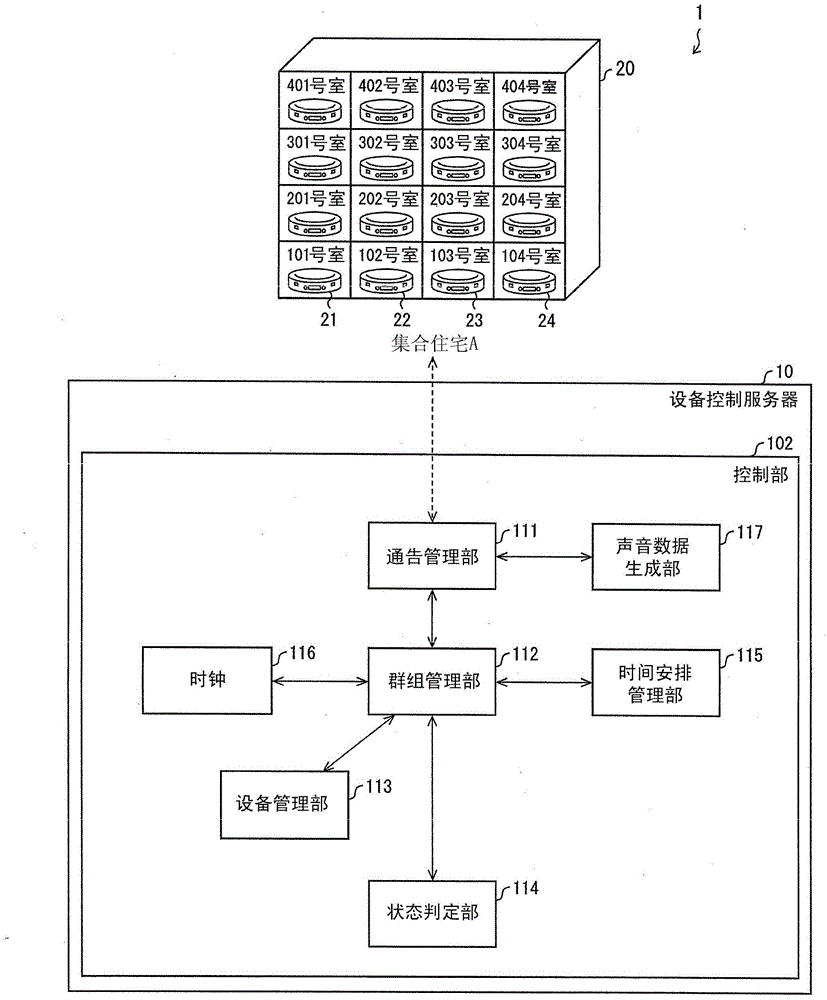
[0033] In the device control system 1 including the device control server 10 according to this embodiment, a group in which a plurality of home appliances are registered is used as a unit, and the users of the home appliances belonging to the group send notices, messages, information about the area where they live, etc. Sharing of information, etc., for the purpose of improving the convenience of the user's life.
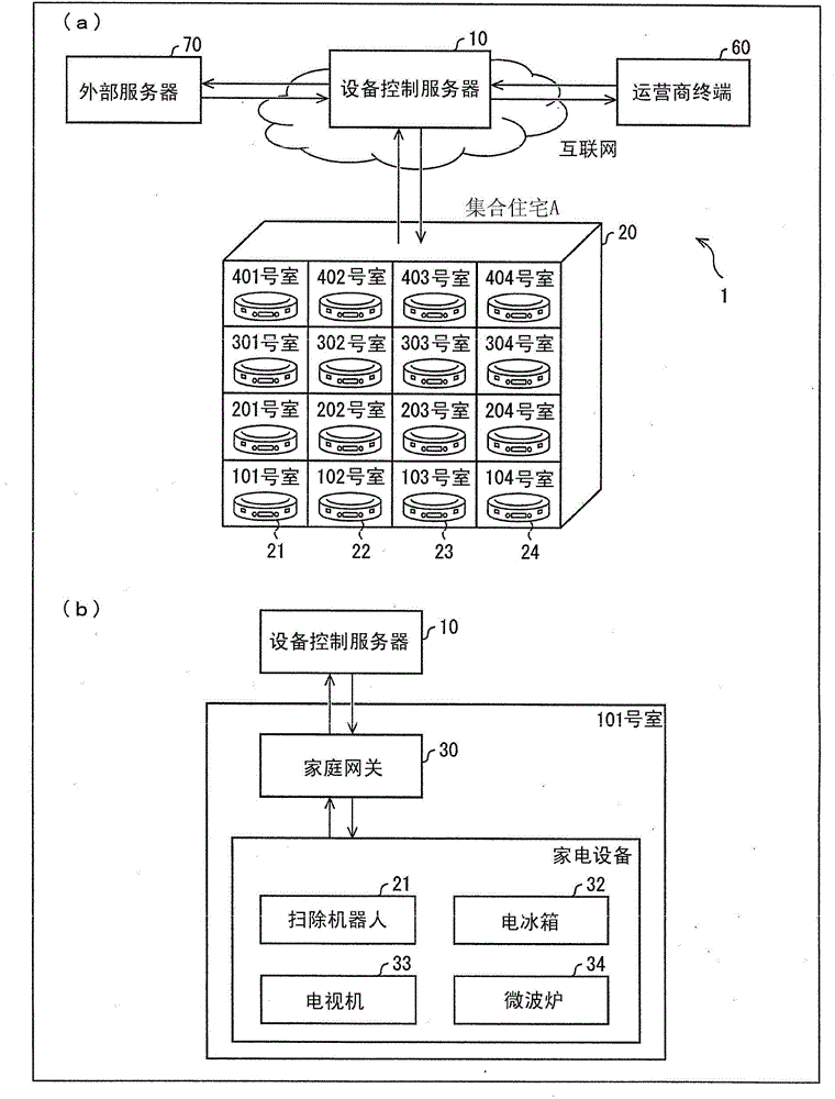
[0034] The facility control system 1 registers not users but electrified products in groups within the facility control system 1 . Specifically, electrical product identification information (device numbers) uniquely assigned to electrical products connected to the device control server 10 in a communicable manner are registered in groups within the device control system 1 . In addition, the electrified products registered in the group in the device control system 1 may be household electrical appliances mainly used at home, or may be business-use devices mainly use...
Embodiment approach 2
[0183] if based on Figure 9 Other embodiments of the present invention will be described as follows. In addition, for convenience of description, members having the same functions as those described in the above-mentioned embodiments are assigned the same reference numerals, and their descriptions are omitted.
[0184] Steps S102 to S114 and step S118 are the same as the respective steps described in the first embodiment. Therefore, its description is omitted here.
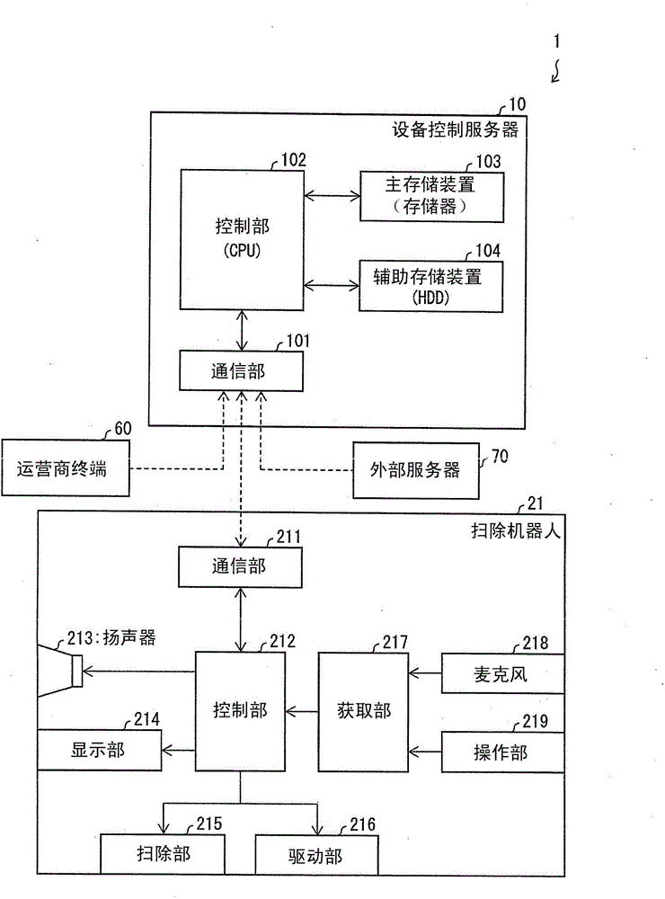
[0185] Step S216 : The communication unit 211 of the cleaning robot 21 supplies (i) utterance voice data received from the device control server 10 and (ii) a control signal for uttering the utterance voice data to the control unit 212 . At this point in time, the cleaning robot 21 receives an instruction from the resident of room No. 101 as the user, and is cleaning.
[0186] The control unit 212 included in the cleaning robot 21 according to the present embodiment includes a notification device status determ...
Embodiment approach 3
[0201] if based on Figure 8 as well as Figure 10-11 Other embodiments of the present invention will be described as follows. In addition, for convenience of description, members having the same functions as those described in the above-mentioned embodiments are assigned the same reference numerals, and descriptions thereof are omitted.
[0202] Figure 8 It is a functional block diagram showing the configuration of the device control server 10 according to this embodiment. Compared with the device control server 10 according to Embodiment 1, the device control server 10 according to this embodiment further includes: a voice information recognition unit 222 and an utterance content determination unit 223 .
[0203]In this embodiment, the acquiring unit 217 of the cleaning robot 21 acquires the voice of the user's inquiry via the microphone 218 as inquiry voice data, and supplies it to the control unit 212 .
[0204] The voice data transmission unit 233 of the control unit...
PUM
 Abstract
Description
Claims
Application Information